Pioneer DEH-X3600UI Owner's Manual - Page 15
DIN front/rear mount, Removing and re-attaching the, front panel, Securing the front panel
 |
View all Pioneer DEH-X3600UI manuals
Add to My Manuals
Save this manual to your list of manuals |
Page 15 highlights
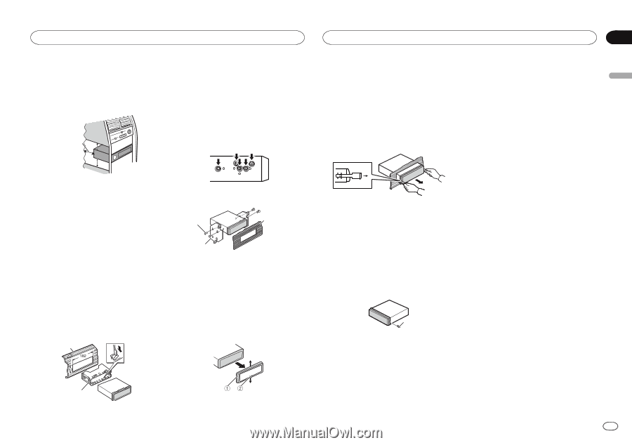
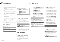
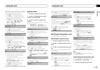
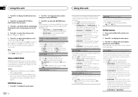
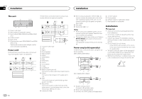
Installation Installation ! When installing, to ensure proper heat dispersal when using this unit, make sure you leave ample space behind the rear panel and wrap any loose cables so they are not blocking the vents. Leave ample space 5 cm 2 Mounting sleeve # Make sure that the unit is installed securely in place. An unstable installation may cause skipping or other malfunctions. DIN Rear-mount 1 Determine the appropriate position where the holes on the bracket and the side of the unit match. 5 cm 5cm ! Releasing the front panel allows easier access to the trim ring. ! When reattaching the trim ring, point the side with the notched tab down. 2 Insert the supplied extraction keys into both sides of the unit until they click into place. 3 Pull the unit out of the dashboard. DIN front/rear mount This unit can be properly installed using either front-mount or rear-mount installation. Use commercially available parts when installing. 2 Tighten two screws on each side. 1 3 DIN Front-mount 1 Insert the mounting sleeve into the dashboard. For installation in shallow spaces, use the supplied mounting sleeve. If there is enough space, use the mounting sleeve that came with the vehicle. 2 1 Screw 2 Mounting bracket 3 Dashboard or console ! Use either truss (5 mm × 8 mm) or flush sur- face (5 mm × 9 mm) screws, depending on the bracket screw holes. 2 Secure the mounting sleeve by using a screwdriver to bend the metal tabs (90°) into place. 1 Removing the unit 1 Remove the trim ring. Removing and re-attaching the front panel You can remove the front panel to protect your unit from theft. For details, refer to Removing the front panel and Re-attaching the front panel on page 4. Securing the front panel The front panel can be secured with the supplied screw. 1 1 Screw 2 1 Dashboard 1 Trim ring 2 Notched tab Section 03 En 15 English
-
 1
1 -
2
-
3
-
4
-
5
-
6
-
7
-
8
-
9
-
 10
10 -
 11
11 -
 12
12 -
 13
13 -
 14
14 -
 15
15 -
 16
16 -
 17
17 -
 18
18 -
 19
19 -
 20
20 -
21
-
22
-
23
-
24
-
25
-
26
-
27
-
28
-
29
-
30
-
31
-
32
-
33
-
34
-
35
-
36
-
37
-
38
-
39
-
40
-
41
-
42
-
43
-
44
-
45
-
46
-
47
-
48
-
49
-
50
-
51
-
52
-
53
-
54
-
55
-
56
-
57
-
58
-
59
-
60
-
61
-
62
-
63
-
64
 |
 |