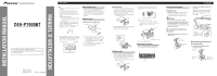
Pioneer DEHP7900BT Other Manual - Page 2
Installation, ENGLISH, Connecting the Units - wiring
 |
UPC - 012562853215
View all Pioneer DEHP7900BT manuals
Add to My Manuals
Save this manual to your list of manuals |
Page 2 highlights
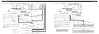
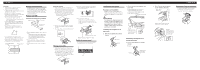
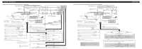
Installation 2. Install the microphone clip on the steering column. Double-sided tape ENGLISH Adjusting the microphone angle The microphone angle can be adjusted by moving forward or backward the microphone clip angle. Install the microphone clip on the rear side of the steering column. Clamps Use clamps to secure the lead where necessary inside the vehicle. Connecting the Units ENGLISH Note: • When this unit is installed in a vehicle without ACC (accessory) position on the ignition switch, red cable must be wired to the terminal that can detect the operation of the ignition key. Otherwise, battery drain may result. F ACC O F O OF OF N STAR N STAR T T ACC position No ACC position • Use this unit in other than the following conditions could result in fire or malfunction. - Vehicles with a 12-volt battery and negative grounding. - Speakers with 50 W (output value) and 4 ohm to 8 ohm (impedance value). • To prevent short-circuit, overheating or malfunction, be sure to follow the directions below. - Disconnect the negative terminal of the battery before installation. - Secure the wiring with cable clamps or adhesive tape. To protect the wiring, wrap adhesive tape around them where they lie against metal parts. - Place all cables away from moving parts, such as gear shift and seat rails. - Place all cables away from hot places, such as near the heater outlet. - Do not pass the yellow cable through a hole into the engine compartment to connect to a battery. - Cover any disconnected cable connectors with insulating tape. - Do not remove RCA caps if RCA cables are not used. - Do not shorten any cables. - Never cut the insulation of the power cable of this unit in order to share the power to other equipment. Current capacity of the cable is limited. - Use a fuse of the rating prescribed. - Never wire the speaker negative cable directly to ground. - Never band together multiple speaker's negative cables. • Control signal is output through blue/white cable when this unit is powered on. Connect it to an external power amp's system remote control or the vehicle's auto-antenna relay control terminal (max. 300 mA, 12 V DC). If the vehicle is equipped with a glass antenna, connect it to the antenna booster power supply terminal. • Never connect blue/white cable to external power amp's power terminal. Also, never connect it to the power terminal of the auto antenna. Otherwise, battery drain or malfunction may result. • IP-BUS connectors are color-coded. Be sure to connect connectors of the same color. • Black cable is ground. This cable and other product's ground cable (especially, high-current products such as power amp) must be wired separately. Otherwise, fire or malfunction may result if they are accidentally detached. • Cord function may differ according to the product, even if cord color is the same. When connecting this system, be sure to check all manuals and connect cords correctly.
-
 1
1 -
 2
2 -
 3
3 -
 4
4 -
 5
5 -
 6
6
 |
 |
