Pioneer DJM-2000nexus Operating Instructions - Page 7
Connections - dj
 |
View all Pioneer DJM-2000nexus manuals
Add to My Manuals
Save this manual to your list of manuals |
Page 7 highlights
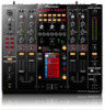
English Connections Be sure to turn off the power and unplug the power cord from the power outlet whenever making or changing connections. Refer to the operating instructions for the component to be connected. Connect the power cord after all the connections between devices have been completed. Be sure to use the included power cord. Rear Panel 12 345 6 375 8 9 6 3 7 52 345 a CH 4 SIGNAL GND PHONO CD L CH 3 LINE CD L CH 2 LINE CD L CH 1 SIGNAL GND PHONO CD L OFF POWER ON CD DIGITAL CONTROL CD DIGITAL OUT DIGITAL IN CONTROL CD DIGITAL CD DIGITAL R R R R MASTER1 R L 1GND 2HOT MASTER2 REC OUT L BOOTH CH 4 CH 3 SEND CH 2 CH 1 RETURN CH 3 CH 1 COMPUTER 1 (TRS) MIDI OUT USB AC IN 3COLD -6dB -3dB 0dB R L R L(MONO) R L(MONO) LINK MASTER R ATT. CH 4 CH 2 COMPUTER 2 l k ji h g 1 POWER (page 13) Turns this unit's power on and off. 2 PHONO (page 8) Connect to a phono level (MM cartridge) output device. Do not input line level signals. 3 CD (page 8) Connect to a DJ player or a line level output component. 4 SIGNAL GND (page 8) Connect an analog player's ground wire here. This helps reduce noise when the analog player is connected. 5 CD, DIGITAL (page 13) Selects the analog signal input terminals (CD) or the digital signal input terminals (DIGITAL IN). 6 LINE (page 8) Connect to a cassette deck or a line level output component. 7 CONTROL (page 8) Connect using a control cord (included with Pioneer DJ players). 8 DIGITAL OUT (page 8) Outputs the master channel audio signals. 9 DIGITAL IN (page 8) Connect these to the digital coaxial output terminals on DJ players, etc. The sound may be momentarily interrupted when the output signal sampling frequency is switched. a Kensington security slot b USB (page 9) Connect to a computer. c MIDI OUT (page 8) Connect this to the MIDI IN terminal on an external MIDI sequencer. d LINK (page 8) Connect these to the LINK terminals on Pioneer DJ players or the LAN ports of computers on which rekordbox is installed (PRO DJ LINK). e RETURN (page 8) Connect to the output terminal of an external effector. When the [L (MONO)] channel only is connected, the [L (MONO)] channel input is simultaneously input to the [R] channel. f SEND (page 8) Connect to the input terminal of an external effector. When the [L (MONO)] channel only is connected, a monaural audio signal is output. g BOOTH (page 8) Output terminals for a booth monitor, compatible with balanced or unbalanced output for a TRS connector. f e d c b h REC OUT (page 8) This is an output terminal for recording. i MASTER2 (page 8) Connect to a power amplifier, etc. j MASTER ATT. Switches the attenuation level of the sound output from the [MASTER1] and [MASTER2] terminals. Select 0 dB, -3 dB or -6 dB. k MASTER1 (page 8) Connect to a power amplifier, etc. l AC IN Connect to a power outlet using the included power cord. Wait until all connections between the equipment are completed before connecting the power cord. Be sure to use the included power cord. En 7
-
 1
1 -
 2
2 -
 3
3 -
 4
4 -
 5
5 -
 6
6 -
 7
7 -
 8
8 -
 9
9 -
 10
10 -
 11
11 -
 12
12 -
13
-
14
-
15
-
16
-
17
-
18
-
19
-
20
-
21
-
22
-
23
-
24
-
25
-
26
-
27
-
28
-
29
-
30
-
31
-
32
-
33
-
34
-
35
-
36
-
37
-
38
-
39
-
40
-
41
-
42
-
43
-
44
-
45
-
46
-
47
-
48
-
49
-
50
-
51
-
52
-
53
-
54
-
55
-
56
-
57
-
58
-
59
-
60
 |
 |
