Pioneer DJM-300 Owner's Manual - Page 6
Connections, Connexion
 |
View all Pioneer DJM-300 manuals
Add to My Manuals
Save this manual to your list of manuals |
Page 6 highlights
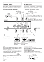
CONNECTIONS CONNEXION Before making or changing the connections, switch off the power switch and disconnect the power cord from the AC outlet. 1. Connection of Input Equipment Avant d'effectuer les raccordement, ou de les modifier, veillez à couper l'alimentation et à débrancher la fiche du cordon d'alimentation. 1. Connexion des appareils d'entrée DAT, etc. DAT, etc... CD2 CDJ-500/ CDJ-500 CD1 CDJ-500/ CDJ-500 DJM-300 L R L R L R Commercially available cord with mini plug (no resistor) (By connecting to CDJ-500, CDJ500 , the fader start function can be used.) Cordon commercialement disponible avec mini-prise (sans résistor). (En raccordant le matériel à une installation CDJ-500 ou CDJ-500 , il est possible d'utiliser la fonction d'activation de la mise en veille.) L L L L SIGNAL L L GND R 1 MASTER OUT R 2 LINE R PHONO PHONO 2 /LINE 2 R CONTROL LINE CD 2 R PHONO PHONO 1 /LINE 1 R CONTROL CD 1 MIC Microphone Microphone L R R L R L To an AC wall socket Prise secteur murale Analog Player 2 (MM Output) Lecteur Analogique 2 (sortie MM). Analog Player 1 (MM Output) Lecteur Analogique 1 (sortie MM). Cassette deck, etc. Lecteur de cassette, etc... NOTE: When connecting the analog players to PHONO1/LINE1 and PHONO2/LINE2 terminals, set the input source selection switch on the rear panel to "PHONO". REMARQUE: Lors de la connexion de lecteurs analogiques sur PHONO1/ LINE1 et PHONO2/LINE2, placer le sélecteur de source d'entrée du panneau arrière sur "PHONO". \ LINE PHONO When not using the analog player, set the switch to "LINE" (See page 9). En n'utilisant pas de lecteurs analogiques, placer ce sélecteur sur "LINE". (Voir page 9). 6 En/Fr Connecting audio cords Use cords with red and white pin plugs. Connect the white plug to (L) and the red plug to (R). Be sure to insert completely. Connexion des câbles audio Utilisez des câbles munis de fiches rouge et blanche. Raccordez la fiche blanche sur (L) et la fiche rouge sur (R). Veillez à les enfoncer complètement. White plug L Fiche blanche Red plug R Fiche rouge
-
 1
1 -
 2
2 -
 3
3 -
 4
4 -
 5
5 -
 6
6 -
 7
7 -
 8
8 -
 9
9 -
 10
10 -
 11
11 -
 12
12 -
13
-
14
-
15
-
16
-
17
-
18
-
19
-
20
 |
 |
