Pioneer DJM-S9 Operating Instructions - Page 12
Front panel
 |
View all Pioneer DJM-S9 manuals
Add to My Manuals
Save this manual to your list of manuals |
Page 12 highlights
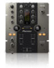
5 CD/LINE input terminal Connect to a DJ player or a line level output component. 6 PHONO input terminals Connect to an analog player or other phono level (MM cartridge) output device. Do not connect to a DJ player or other line level device. To connect a device to the [PHONO] terminals, remove the shortcircuit pin plug inserted in the terminals. Insert this short-circuit pin plug into the [PHONO] terminals when nothing is connected to them to cut external noise. WARNING The short-circuit pin plugs out of the reach of children and infants. If accidentally swallowed, contact a doctor immediately. 7 SIGNAL GND terminal Connects an analog player's ground wire here. This helps reduce noise when the analog player is connected. 8 MIC input terminals Connects a microphone here. 9 MIC input level selector switch - [MIC]: Select this when connecting the microphone to the [MIC] terminal. - [LINE]: Select this when connecting line level output devices to the [MIC] terminal. a Kensington security slot b USB terminal Connect to a computer. c POWER switch Turns this unit's power on and off. d AUX input terminal Connect to the output terminal of an external device (sampler, portable audio device, etc.) e AC IN Connects to a power outlet using the included power cord. Wait until all connections between the equipment are completed before connecting the power cord. Be sure to use the included power cord. Front panel 34 5 8 a b 6 79 1 PHONES jacks Connect headphones here. This product supports 1/4" stereo phone plugs and 3.5 mm stereo mini plugs. 2 CROSS FADER CURVE adjustment control Adjusts the crossfader curve characteristics. 3 MIC ON OFF selector switch Turns the microphone on/off. 4 MIC TALK OVER selector switch Turns on and off the talk-over function while the microphone is turned on. 5 MIC indicator Turns on and off the talk-over function while the microphone is turned on. - While the MIC is off: The light is off. - While the MIC is on: The light is on. - While talking over: The light blinks. 6 MIC LEVEL control Adjusts the level of the sound output from the [MIC] channel. 7 MIC EQ (HI, LOW) control Adjusts the sound quality of the [MIC] channel. 12 En cd d c2 1 e 8 MIC ECHO control Adjusts the parameter of echo effect applied to the [MIC] channel. 9 AUX LEVEL control Adjusts the level of the sound input to the AUX channel. a CROSS FADER FEELING ADJUST control This can be used to adjust the crossfader's operating load. b CROSS FADER REVERSE switch Turns the crossfader reverse function on and off. c CH FADER CURVE adjustment control Adjusts the curve characteristics of the corresponding channel fader. d CH FADER REVERSE switch Turns on and off the reverse function of the corresponding channel fader. e Front guard Protects the terminals and controls on the front panel. Do not use it as a foot of the product. The unit may tip over.
-
 1
1 -
2
-
3
-
4
-
5
-
6
-
 7
7 -
 8
8 -
 9
9 -
 10
10 -
 11
11 -
 12
12 -
 13
13 -
 14
14 -
 15
15 -
 16
16 -
 17
17 -
18
-
19
-
20
 |
 |
