Pioneer DV-353-K Service Manual
Pioneer DV-353-K Manual
 |
View all Pioneer DV-353-K manuals
Add to My Manuals
Save this manual to your list of manuals |
Pioneer DV-353-K manual content summary:
- Pioneer DV-353-K | Service Manual - Page 1
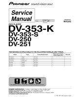
DV-353-K DVD PLAYER DV-353-K DV-353-S DV-250 DV-251 ORDER NO. RRV2592 THIS MANUAL IS APPLICABLE TO THE FOLLOWING MODEL(S) AND TYPE(S). Model Type Power Requirement Regional restriction codes (Region No.) DV-353-K KUXJ AC120V 1 DV-353-K KCXJ AC120V 1 DV-353-S KUXU/CA AC120V 1 DV - Pioneer DV-353-K | Service Manual - Page 2
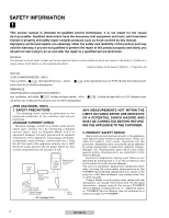
Safety is continuously under review and new instructions are issued from time to time. For the latest information, always consult the current PIONEER Service Manual. A subscription to, or additional copies of, PIONEER Service Manual may be obtained at a nominal charge from PIONEER. 2 DV-353-K - Pioneer DV-353-K | Service Manual - Page 3
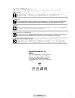
Discs compatible with this player Any disc that displays one of the following logos should play in this player. Other formats, including DVD-Audio, DVD-RAM, DVD-ROM, CD-ROM (except those that contain MP3 files), SACD and Photo CD will not play. DVD-Video Audio-CD Video-CD CD-R CD-RW DV-353-K 3 - Pioneer DV-353-K | Service Manual - Page 4
CONTENTS 1. SPECIFICATIONS ...5 2. EXPLODED VIEWS AND PARTS LIST ...6 2.1 PACKING ...6 2.2 EXTERIOR SECTION ...8 2.3 LOADING MECHANISM ASSY ... TROUBLE SHOOTING ...68 7.1.5 SEQUENCE AFTER THE POWER ON ...70 7.1.6 DISASSEMBLY ...71 7.2 IC ...76 7.3 CLEANING ...94 8. PANEL FACILITIES ...95 4 DV-353 - Pioneer DV-353-K | Service Manual - Page 5
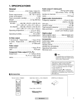
1. SPECIFICATIONS General System DVD-Video, Video CD, CD and MP3 files Power requirements AC 120 V, 60 Hz Power consumption 13 W Power consumption (standby 0.3 W Weight 2.4 kg (5lb 5oz) Dimensions DV-353 420 (W) x 55 (H) x 278 (D) mm (16 9/16 (W) x 23/16 (H) x 1015/16 (D) in.) DV-250/251 - Pioneer DV-353-K | Service Manual - Page 6
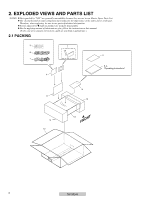
on product are used for disassembly. For the applying amount of lubricants or glue, follow the instructions in this manual. (In the case of no amount instructions, apply as you think it appropriate.) 2.1 PACKING 3 8 1 4 7 14 2 5, 6 "Operating Instructions" 4 11 10 9 12 13 FRONT 6 DV-353-K - Pioneer DV-353-K | Service Manual - Page 7
constructed the same except for the following : Part No. Mark No. Symbol and Description DV-353-K DV-353-S DV-250 DV-251 Remarks KUXJ KCXJ KUXU/CA KUXU KCXU KUXQ NSP NSP 2 Warranty Card 3 Dry Cell Battery (R6P, AA) 6 Operating Instructions (French) 9 Pad L 10 Pad R ARY7057 ARY7045 ARY7057 - Pioneer DV-353-K | Service Manual - Page 8
22 22 C D E F 14 B 6 A 23 23 22 19 20 24 24 2 24 D 16 24 24 24 24 C 24 24 17 24 A 14 3 9 15 18 21 16 8 DV-353-K - Pioneer DV-353-K | Service Manual - Page 9
RNH-184 NSP 11 Pcb Support 12 Base Chassis 13 Rear Panel 14 PCB Base 15 DVD V Plate VEC2184 See DV-353-K/KUXJ, KCXJ, DV-353-S/KUXU/CA, DV-250/KUXU, KCXU and DV-251/KUXQ are constructed the same except for the following : Part No. Mark No. Symbol and Description DV-353-K DV-353-S DV-250 DV - Pioneer DV-353-K | Service Manual - Page 10
Oil GYA1001 18 20 3 13 23 A 22 17 16 4 5 22 19 15 14 9 22 21 7A 11 A1 22 22 10 Lubricating Oil GYA1001 10 DV-353-K - Pioneer DV-353-K | Service Manual - Page 11
Contrast table (2) VKP2253 VEB1327 VEB1330 VNE2253 11 Loading Base 12 Float Base DVD 13 Drive Cam 14 Gear Pulley 15 Loading Gear VNL1917 VNL1918 VNL1919 VNL1921 VWT1196 Part No. VWT1197 VWT1188 NSP 1 LOAB Assy 6 Flexible Cable (26P) VWG2346 VDA1864 VWG2279 VDA1865 Remarks DV-353-K 11 - Pioneer DV-353-K | Service Manual - Page 12
No. 13 Drive Cam Daifree GEM1036 Concave of unevenness Top View 12 Inner side of a ditch Daifree GEM1036 Concave of unevenness Daifree GEM1036 Bottom View DV-353-K Side of the rib Daifree GEM1036 - Pioneer DV-353-K | Service Manual - Page 13
DV-353-K 13 - Pioneer DV-353-K | Service Manual - Page 14
Adhesive GEM1037 17 (Torque : 0.12 ± 0.01 N•m) 5 5 15 Screw Tight GYL1001 Silicone Adhesive GEM1037 17 (Torque : 0.12 ± 0.01 N•m) 16 2 NON-CONTACT SIDE 11 CONTACT SIDE 14 DV-353-K - Pioneer DV-353-K | Service Manual - Page 15
Spring 9 Joint Spring 10 Support Spring VLL1514 VLL1515 VNC1017 VNC1019 VNC1020 NSP 11 Mechanism Chassis 12 Slider 13 Spacer 14 Joint 15 FFC Holder VNE2248 VNL1811 VNL1913 VNL1914 VNL1915 16 Screw 17 Tapping Screw 18 Screw 19 Damper Sheet BBZ20P050FZK OBA8009 PMA26P100FMC VEB1335 DV-353-K 15 - Pioneer DV-353-K | Service Manual - Page 16
• Main Unit Key Input 4 X2 • Remote Control Receive • FL Display Control IR KEY1 KEY0 17 21 22 V11 FL TUBE CN11 (5P) 5 2 1 IR KEY1 KEY0 5 2 1 CN301 (5P) REMOTE RECEIVER UNIT IC301 SPS-444L-H KEY3 1 1 J301 (3P) C IRKY ASSY F D AC IN PSWB ASSY 16 DV-353-K 1 2 3 4 - Pioneer DV-353-K | Service Manual - Page 17
OUT C R721 4 7 R722 8 3 R723 5 6 1 BCKIN IC711 Vout L 7 LOUT 2 DATA PCM1742KE Audio 2ch DAC 16 MCLK 3 LRCKIN Vout R 8 ROUT AUDIO LPF BA4560F IC731-1/2 2 1 3 IC731-2/2 5 7 6 L AUDIO OUT R D E F DV-353-K 17 5 6 7 8 - Pioneer DV-353-K | Service Manual - Page 18
V+3E CN301 (5P) 3 CN52 (5P) 4 V+3R5D IC441 IC303 PQ070XZ02ZP +3.5V Reg. V+3R5D V+3R5A BA18BC0FP +1.8V Reg. V+1RBD V+1RBA1 V+1RBA2 VIN VOUT 1 3 2 CN11 (5P) 3 V+3E E F 18 DV-353-K 1 2 3 4 - Pioneer DV-353-K | Service Manual - Page 19
B FJMB ASSY Measurement condition : No. 1 to 2 and 9 to 14 : reference A1 (DVD), T2-chp 19, Color-bar No. 3 to 8 : reference A1 (DVD), T2-chp 1 1 IC301 - pin 3 [RF] V: 200mV/div. H: 0.1µsec/div. H: 500nsec/div. V: 2V/div. H: 500nsec/div. V: 2V/div. H: 2msec/div. E F DV-353-K 19 5 6 7 8 - Pioneer DV-353-K | Service Manual - Page 20
1 2 3 4 3.2 LOAB ASSY and OVERALL WIRING DIAGRAM A B C D B FJMB ASSY (VWS1515) E PB PR F ABCDE 20 DV-353-K 1 2 3 4 - Pioneer DV-353-K | Service Manual - Page 21
5 6 7 8 Note : When ordering service parts, be sure to refer to "EXPLODED VIEWS and PARTS LIST" or "PCB PARTS LIST" A C IRKY ASSY (VWG2344) for MOTOR (S) : VXM1090 (S) (S) (S) E SPINDLE MOTOR : VXX1088 A LOAB ASSY (VWG2279) LOADING MOTOR ASSY : VXX2505 F ABCDA DV-353-K 21 5 6 7 8 - Pioneer DV-353-K | Service Manual - Page 22
1 2 3 4 3.3 FJMB ASSY 1/5 [FRONT END BLOCK] A B 1/5 FJMB ASSY (VWS1515) B 2/5 (S) B A CN601 C PICKUP ASSY (F) (F) (T) D (T) (F) (F) (S) E STEPPING (S) MOTOR (S) (S) 17 2 SPINDLE MOTOR F B 1/5 22 DV-353-K 1 2 3 4 - Pioneer DV-353-K | Service Manual - Page 23
5 6 7 8 A B 2/5 B 1, 2, #, $: Refer to "3.1.3 WAVEFORMS". (F) : FOCUS SERVO LOOP LINE (T) : TRACKING SERVO LOOP LINE (S) : SLIDER SERVO LOOP LINE C VCC33DAC 1 VCC18MN D 16 E (F) (F) (F) (F) (T) (T) F B 1/5 DV-353-K 23 5 6 7 8 - Pioneer DV-353-K | Service Manual - Page 24
(8M) (D) B 3/5 1 2 3 4 3.4 FJMB ASSY 2/5 [BACK END BLOCK] A B 2/5 FJMB ASSY (VWS1515) B 15 C D (B/Cb) (G/Y) (R/Cr) (S_Y) (S_C) (V) E (D) F B 2/5 B 5/5 B 2/5 B 1/5 24 DV-353-K 1 2 3 4 - Pioneer DV-353-K | Service Manual - Page 25
) : V SIGNAL ROUTE : S-VIDEO OUT C SIGNAL ROUTE : S-VIDEO OUT Y SIGNAL ROUTE : R/Cr SIGNAL ROUTE : G/Y SIGNAL ROUTE : B/Cb SIGNAL ROUTE : AUDIO SIGNAL ROUTE (D) : AUDIO(DIGITAL) SIGNAL ROUTE D E F B 2/5 DV-353-K 25 5 6 7 8 - Pioneer DV-353-K | Service Manual - Page 26
1 2 3.5 FJMB ASSY 3/5 [AUDIO BLOCK] A B 2/5 3 4 B 3/5 FJMB ASSY (VWS1515) B 47 8 3 56 C D E F B 3/5 26 DV-353-K 1 2 3 4 - Pioneer DV-353-K | Service Manual - Page 27
5 6 7 8 A 3- 8: Refer to "3.1.3 WAVEFORMS". : AUDIO SIGNAL ROUTE B C B 4/5 D E : The power supply is shown with the marked box. F B 3/5 DV-353-K 27 5 6 7 8 - Pioneer DV-353-K | Service Manual - Page 28
1 2 3.6 FJMB ASSY 4/5 [VIDEO BLOCK] A B 4/5 FJMB ASSY (VWS1515) 3 (D) B 2/5 B (D) (D) 4 (D) C (S_C) D (V) (S_Y) (G/Y) (B/Cb) (R/Cr) E (S_C) (V) (S_Y) (G/Y) (B/Cb) (R/Cr) F B 4/5 28 DV-353-K 1 2 3 4 - Pioneer DV-353-K | Service Manual - Page 29
ROUTE (R/Cr) : R/Cr SIGNAL ROUTE (D) : AUDIO(DIGITAL) SIGNAL ROUTE B (D) (S_Y) 13 14 C (S_C) 9 (V) (S_C) (V) D 10 (G/Y) (S_Y) 12 (G/Y) (R/Cr) 11 (B/Cb) (B/Cb) (R/Cr) E B 3/5 9- !: Refer to "3.1.3 WAVEFORMS". F B 4/5 DV-353-K 29 5 6 7 8 - Pioneer DV-353-K | Service Manual - Page 30
1 2 3 4 3.7 FJMB ASSY 5/5 [FL CONTROL BLOCK] A B 5/5 FJMB ASSY (VWS1515) B C D E F B 5/5 30 DV-353-K 1 2 3 4 - Pioneer DV-353-K | Service Manual - Page 31
5 6 7 8 A B A CN601 C B 2/5 D E F B 5/5 DV-353-K 31 5 6 7 8 - Pioneer DV-353-K | Service Manual - Page 32
1 2 3 4 3.8 IRKY and PSWB ASSYS A S301 : 0 OPEN/CLOSE S302 : 3 S303 : 8 S304 : 7 S305 : ¡ ¢ S306 : 4 1 B B 5/5 CN11 C C IRKY ASSY (VWG2344) D E F C 32 DV-353-K 1 2 3 4 - Pioneer DV-353-K | Service Manual - Page 33
5 6 7 8 A B S401 : STANDBY/ON C D PSWB ASSY (VWG2345) D for ##XCN type : The power supply is shown with the marked box. E F D DV-353-K 33 5 6 7 8 - Pioneer DV-353-K | Service Manual - Page 34
Please take care to keep the space, not touching other parts when replacing the parts. CN1 REK1077 1.6A AEK7063 800mA CAUTION : FOR CONTINUED PROTECTION (AEK7067). CN101 AEK7066 1.6A AEK7067 2.0A AEK7012 1.6A B 1/3 CN401 2 2 DV-353-K 3 3 4 E 4 C2, C6, C106, C303, Z1: STANDBY • NOTE - Pioneer DV-353-K | Service Manual - Page 35
• Please take care to keep the space, not touching other parts when replacing the parts. CAUTION : FOR CONTINUED PROTECTION AGAINST RISK OF FIRE. REPLACE TYPE NO. 491002 MFD, BY LITTELFUSE INC. FOR CP1 (AEK7067). 6 6 DV-353-K 7 7 REK1077 1.6A CN1 AC IN AEK7012 1.6A AEK7063 800mA AEK7066 1. - Pioneer DV-353-K | Service Manual - Page 36
1 2 3 4 A B C D E F 36 DV-353-K 1 2 3 4 - Pioneer DV-353-K | Service Manual - Page 37
sure to check with the schematic diagram. 4. View point of PCB diagrams. Connector Capacitor SIDE A B P.C.Board Chip Part SIDE B Resistor array 3-terminal regulator C D 4.1 LOAB ASSY A LOAB ASSY M LOADING MOTOR ASSY CN11 B CN52 SIDE A (VNP1836-B) A 5 DV-353-K 6 SIDE B 7 E F A 37 8 - Pioneer DV-353-K | Service Manual - Page 38
IC304 IC271 IC251 Q105 IC110 Q601 IC605 Q271 Q103 Q104 IC303 IC603 Q272 Q101 Q102 IC111 IC604 IC601 C605 R574 R588 R589 R663 C606 F B 38 DV-353-K 1 2 3 4 - Pioneer DV-353-K | Service Manual - Page 39
IN SOLDER AND CERTAIN ELECTRICAL PARTS CONTAIN CHEMICALS WHICH ARE KNOWN DEFECTS OR OTHER REPRODUCTIVE HARM. HEALTH & SAFETY CODE SECTION 25249.2 - PROPOSITION 65 17 C803 R944 Q603 Q605 Q711 IC771 IC711 Q772 IC921 Q771 IC901 DV-353-K 5 6 Q796 Q762 IC731 Q761 Q794 Q792 Q791 Q795 IC801 Q941 - Pioneer DV-353-K | Service Manual - Page 40
GNDD MCLK GNDD GNDD LRCLKIN ADATA0IN BCKIN BCKOUT ADATA0OUT LRCLKOUT +5V +5V KDSPTHRU GNDA KDSPXCS XRESET 44X48 MIC GND R560 R607 13 3 3 Q652 DV-353-K Q776 Q777 Q808 Q807 Q806 Q805 CN903 CN901 CN902 CN1001 20 1 CN950 Q651 R652 R671 R666 R668 Q805 Q806 +12V +5V MICON2 MIC XAMUTE2 - Pioneer DV-353-K | Service Manual - Page 41
R18 V+3E CN11 R26 R25 5 IR GND EV3IR KEY1 KEY0 R350 1 CN12 13 1 R294 R291 C272 R293 C299 R299 C12 R19 R20 C13 R21 R22 DV-353-K Q275 Q275 6 6 R328 R327 EV3 GND -28V FLDC+ FLDCP-ON LT1 XRESET XREADY S(FtoM) S(MtoF) SCK GND V+6A V+12M V+6B CN61 CN251 FJMB Q274 Q273 - Pioneer DV-353-K | Service Manual - Page 42
/ IR CLOSE PLAY GND V+3E KEY1 KEY0 R322 D301 POWER ON VWG 1 31 GND KEY0 CN401 GND KEY0 VWG2345- 1 CMKS-P3X GND PSWB 3 E 1 D PSWB ASSY F CD 42 1 DV-353-K 2 3 CD 4 - Pioneer DV-353-K | Service Manual - Page 43
5 6 7 8 4.4 POWER SUPPLY UNIT (VWR1351) SIDE A AC IN SIDE A A E POWER SUPPLY UNIT B Q2 Q1 Q20 Q320 VR201 IC103 IC201 Q412 Q411 Q410 E 5 DV-353-K 6 7 CN101 B CN401 C D E F E 43 8 - Pioneer DV-353-K | Service Manual - Page 44
1 2 3 4 4.5 POWER SUPPLY UNIT (VWR1353) SIDE A A AC IN SIDE A E POWER SUPPLY UNIT B C IC3 IC2 D IC1 IC4 E Q6 F E 44 1 DV-353-K 2 3 CN2 B CN401 E 4 - Pioneer DV-353-K | Service Manual - Page 45
Parts List. •The mark found on some component parts indicates the importance of the safety factor of the part. Therefore, when replacing, be sure to use parts of identical designation. •When ordering resistors, first convert resistance values into code PST3228 STI5519AVB-B0C TC7WU04FU DV-353-K 45 - Pioneer DV-353-K | Service Manual - Page 46
C601 C610, C611, C613, C615, C629 C635, C636, C741 C734, C754 (330P/50V) Part No. VYW1890 2SA1037K 2SA1602A 2SC2412K 2SD2114K DTC114TK DTC114YK HN1A01F PDTA124EK RN4982 RB501V-40 UDZS6.2B LAU3R3J LCYA2R2J2520 CHIP BEADS SWITCHES AND RELAYS S301-S306 SPS-444L-H VTL1084 ASG7013 46 DV-353-K - Pioneer DV-353-K | Service Manual - Page 47
C301 RESISTORS All Resistors OTHERS 3P CABLE HOLDER J301 3P JUMPER WIRE CN301 CONNECTOR Part No. CKSRYF104Z25 RS1/16S###J 51048-0300 D20PDD0315E S5B-PH-K PSWB ASSY SWITCHES AND 6A) > CP1 PROTECTOR (2A) > F1 FUSE (1.6A) AEK7063 AEK7066 AEK7067 REK1077 Mark No. Description Part No. DV-353-K 47 - Pioneer DV-353-K | Service Manual - Page 48
Part) [Mechanism Part] 1 Tangential and Radial Height Coarse Adjustment 2 DVD Jitter Adjustment 3 Initialize the Focus Sweep Setting [Electrical Part (medium) TV monitor Test mode remote control unit (GGF1067) Precise screwdriver 48 DVD test disc (GGV1025) Screw tight (GYL1001) DV-353-K - Pioneer DV-353-K | Service Manual - Page 49
6.3 NECESSARY ADJUSTMENT POINTS When Exchange Parts of Mechanism Assy Adjustment Points Exchange the Pickup Mechanical point ~, Ÿ, ! ∗ Traverse Mechanism and Spindle Motor. ESC CLEAR GGF1067 Test mode remote control unit (It is necessary when performed adjustment procedure Ÿ.) DV-353-K 49 - Pioneer DV-353-K | Service Manual - Page 50
MODE TEST MODE: ON POWER ON TEST MODE: DISC SET OPEN/CLOSE (Player or Remote Control Unit) DVD disc ESC TEST GGF1067 Test mode remote control unit OPEN/CLOSE (Player or Remote Control Unit) CHECK DVD, CD DSC - &&& TEST MODE: PLAY TV/LDP An address is displayed < When - Pioneer DV-353-K | Service Manual - Page 51
a Spacer for height adjustment in adjustment after the second time, will keep it at need. (This parts is Traverse mechanism exclusive use of a model for 2001 years) 7.3mm Float Base Spacer for Height adjustment Refer to "6.1 ADJUSTMENT ITEMS AND LOCATION".) Turn a flat side into bottom DV-353-K 51 - Pioneer DV-353-K | Service Manual - Page 52
Specification of the Test Mode)". Use disc: GGV1025 START • Test mode • Play the DVD test that jitter becomes minimum. J : Min Player J: ---Monitor • Play the DVD test disc at outer track (around 5 Screw tight: GYL1001 52 DV-353-K Mechanism Assy Readjust the Tangential Adjustment Screw - Pioneer DV-353-K | Service Manual - Page 53
3 Initialize the Focus Sweep Setting Purpose: To set the sweep which was correct with the individual Traverse mechanism. Turn on the Player POWER ESC CLEAR Note: Be sure to perform this step when replaced the Pickup or Traverse mechanism. DV-353-K 53 - Pioneer DV-353-K | Service Manual - Page 54
remote control unit or main unit from the playback state. 5 LD ON DVD : Press the [TEST] (A8-5E) and [1] (A8-01) keys in order, and turn on the laser diode (650n). CD of the remote control unit. 2. Turn on the display by pressing the [DISPLAY] (A8-43) key of the remote control unit. 54 DV-353-K - Pioneer DV-353-K | Service Manual - Page 55
(A8-13) key of the remote control unit. • After the search, perform only trace and video and audio outputs are nothing. 4. Release the Search address input • Clear the address by pressing the [CLEAR] (A8-45) key. Release the address input mode when pressing the [CLEAR] key once again. DV-353-K 55 - Pioneer DV-353-K | Service Manual - Page 56
] 0 Disc sensing [DSC The type of discs loaded is displayed. [DVD], [CD ], [VCD], [ ] - Jitter value [J = Version of the AV-1 chip / version of firmware [AV ~ Version of the FL controller [FL ! Region setting of the player [REG: ∗] Setting value : [1] to [6] @ Destination setting of the FL - Pioneer DV-353-K | Service Manual - Page 57
to A8-09 PLAY (LD remote control unit) A8-17 Region confirmation mode AUDIO (LD remote control unit) A8-1E Numbers (LD remote control unit) A8-01 to A8-08 • Service mode indication ID Address Always display error rate. Exponential indication ∗.∗∗e-∗ (with both DVD and CD) EDC/ID/AV1 error history - Pioneer DV-353-K | Service Manual - Page 58
Specification of Model Information Display • Display contents 3 2 1 4 5 Display it according to model information set from the FL controller. 3 Region No. 4 Part number 5 ROM version 6 Flash size 7 FL controller version 8 CHIP controller CHIP software) / MainVersion / SubVersion 58 DV-353-K - Pioneer DV-353-K | Service Manual - Page 59
Specification of the Service Mode • FL indication of EDC / ID error (short cut function) Display it in FL with ESC+CX keys (LD remote overflow and not valid occur in the BE code (B.E error). BIT 1: ID is different from the target in the BE code (B.E error). BIT 2: There is error in DV-353-K 59 - Pioneer DV-353-K | Service Manual - Page 60
service mode screen display. Indication displayed in the screen upper part is new error. • Indication contents 1 Error code Two characters in the front represent the Error Code timeout DECODER TIMEOUT ID lost timeout FAIL SAFE unexpected error DV-353-K 0x1∗ 0x11 0x12 0x13 0x14 0x15 0x16 0x17 0x3∗ - Pioneer DV-353-K | Service Manual - Page 61
ERROR CODE TABLE Error Name FOCUS ERROR (0 x 0∗) Focus on error Focus off error Focus lost error Focus balance adjust error Focus gain adjust error Focus sweep error Focus reflection error FOCUS TIMEOUT (0 x 1∗) Focus on timeout Focus off timeout No. Causes Check Item Possibility of Trouble - Pioneer DV-353-K | Service Manual - Page 62
x d1 Cannot access SRAM FAILSAFE (0 x e∗) Unexpected error 0 x e1 Unexpected error Check Item Possibility of Trouble Remarks Are not there a dirt or a scratch in the Disc? Is FG output from the driver? Is (Front End IC) 3. L6315-SRAM bus line 1. software runaway 3. Software bug 62 DV-353-K - Pioneer DV-353-K | Service Manual - Page 63
DV-353-K 63 - Pioneer DV-353-K | Service Manual - Page 64
H: 0.1µsec/div. Measurement condition : No. 1 to 2 and 9 to 14 : reference A1 (DVD), T2-chp 19, Color-bar No. 3 to 8 : reference A1 (DVD), T2-chp 1 2 IC251 - pin 24 [FG] V: 1V/div. H: 5msec/div. 3 Composite Video output] V: 1V/div. H: 10µsec/div. 16 IC3 6 7 8 64 DV-353-K 1 2 3 4 - Pioneer DV-353-K | Service Manual - Page 65
µsec/div. 11 12 [PLAY] [STOP] Accelertar ON STOP PLAY Brakes ON STOP V: 2V/div. H: 1sec/div. 5 V: 2V/div. H: 500nsec/div. V: 2V/div. H: 500nsec/div. DV-353-K 6 7 E 13 14 F 65 8 - Pioneer DV-353-K | Service Manual - Page 66
1 SIDE B A B C D E F 66 1 CN1001 2 3 4 FCS_RTN CN401 13 21 CN951 W 15 IC6 V: 1 DV-353-K 2 3 4 - Pioneer DV-353-K | Service Manual - Page 67
] V: 1V/div. H: 5µsec/div. [Tray stops] 5 E [Tray is opening] [Tray is closing] 17 CN251 - pin 12, 11, 10 (IC251 - pin 2, 4, 7) [Spidle driver -A3, A2, A1] DV-353-K 6 7 [PLAY] V: 2V/div. H: 2msec/div. F 67 8 - Pioneer DV-353-K | Service Manual - Page 68
7.1.4 TROUBLE SHOOTING At first confirm error history. ( 0V - 3.3V when I pushed a wireless remote controller key? Wireless remote controller receiver light part (in case of only a key of a wireless remote controller, NG) 2 An opening screen is not does it change? Inside switch 68 DV-353-K - Pioneer DV-353-K | Service Manual - Page 69
up /down? Does not an actuator spring turn? PICKUP Are not resin part damage, a shaft missing? Are not there falling off of turn table, in FG waveform? 650nLD deteriorates. (Cannot playback DVD) 780nLD deteriorates. (Cannot playback CD) FG output: Spindle Driver IC (IC251) (IC711) DV-353-K 69 - Pioneer DV-353-K | Service Manual - Page 70
chart from power on to the picture output STANDBY Power on operation by a user (remote controller key or product key) FL controller receives a message FL controller outputs FL detection (Focus control) Spindle turn 70 DV-353-K ID information code is caught Various setting The picture output - Pioneer DV-353-K | Service Manual - Page 71
is not installed to this. 2 4 35 Tray Panel 35 Tray How to Open the Tray by Manual Operating In the reverse state, pass a small screwdriver through a slit and slide a protruding portion of the the wiring. 3 Unhook (×6) 4 Remove the Front Panel. 3 ×3 4 3 ×3 Front Panel 2 1 DV-353-K 71 - Pioneer DV-353-K | Service Manual - Page 72
4 3 FJMB Assy 3 5 Put the Power Cable in the outlet. 6 Power ON 7 Set the Test Disc. 8 Playback with a test disc, and diagnose the FJMB Assy. 72 DV-353-K - Pioneer DV-353-K | Service Manual - Page 73
Remove the FFC Holder with the state which Flexible Cable was atatched. Traverse Mechanism Assy 10 Silicone Adhesive GEM1037 11 FFC Holder Pin Drive Cam DV-353-K Bottom View 73 - Pioneer DV-353-K | Service Manual - Page 74
. Please lock it with Silicone adhesive when installs it. 15 Slider Hold Spring Silicone Adhesive GEM1037 Pickup Assy Joint Silicone Adhesive 15 GEM1037 Exchange 74 DV-353-K - Pioneer DV-353-K | Service Manual - Page 75
Styling the Pickup Flexible Cable 1 Fold a edge of lining part of the Pickup Flexible Cable. 2 Insert the Pickup Flexible Cable in connector, and lock it position of reference line. 6 Fold position of step 6 Bottom View Reference line Bottom View 55 4 Bottom View DV-353-K 11 12 Bottom View 75 - Pioneer DV-353-K | Service Manual - Page 76
in the schematic diagrams. • List of IC M56788AFP, MM1567AJ, STI5519AVB-B0C, PE5314A, L6315ATXXTY, BA6664FM, PCM1742KE 7 M56788AFP (FJMB ASSY : IC351) • FTS Driver IC ¶ Block Diagram 76 DV-353-K - Pioneer DV-353-K | Service Manual - Page 77
7 MM1567AJ (FJMB ASSY : IC801) • DVD Video Amp IC ¶ Block Diagram ¶ Pin Function No. Name 1 VCC1 2 CIN 3 MUTE1 4 VIN 5 YC MIX 6 YIN 7 BIAS 8 GND1 9 NC 10 correction GND Signal output SAG correction GND Signal output SAG correction GND Signal output SAG correction GND Croma output VCC DV-353-K 77 - Pioneer DV-353-K | Service Manual - Page 78
7 STI5519AVB-B0C (FJMB ASSY : IC601) • Back End IC ¶ Block Diagram 78 DV-353-K - Pioneer DV-353-K | Service Manual - Page 79
supply RGB circuit Ground B / Cb G/Y R / Cr RGB DAC reference RGB DAC electric current reference YC circuit 2.5 V Power supply YC circuit Ground Y C CV YCC DAC reference DV-353-K 79 - Pioneer DV-353-K | Service Manual - Page 80
, LFE data Audio DAC Surround L,R data Audio DAC Master clock Audio DAC L/R clock S/PDIF(IEC60958) digital audio output. OUT SMI SDRAM addresss − 2.5 V Power supply 80 DV-353-K - Pioneer DV-353-K | Service Manual - Page 81
). Karaoke model Exteranal DSP chip select 'L'. In case of NOT Karaoke model, this port is N.C.(output). Karaoke model Exteranal DSP through pass mode 'L'. Pin Functions DV-353-K 81 - Pioneer DV-353-K | Service Manual - Page 82
Open/Close drive PWM output (SINGL & CAROUSEL) 8M / 16M bits FLASH memory for firmware. 64M bits SDRAM for debugging firmware . 2.5 V Power supply Master 27MHz system clock input. Ground Clock PLL circuit 2.5 3.3V Vdd GND TP-x Debug SDRAM CAS 'L' Debug SDRAM Chip Select 'L' 82 DV-353-K - Pioneer DV-353-K | Service Manual - Page 83
OUT − 2.5 V Power supply − Ground OUT − 3.3 V Power supply Pin Functions FLASH, Debug SDRAM DATA FLASH, Debug SDRAM DATA FLASH, Debug SDRAM address FLASH, Debug SDRAM address DV-353-K 83 - Pioneer DV-353-K | Service Manual - Page 84
position. Front Panel interface. Hand-shake (acknowledge) output. Front Panel interface. (Soft) Serial transfer clock output. Front Panel interface. (Soft) Serial transfer data input. 84 DV-353-K - Pioneer DV-353-K | Service Manual - Page 85
: OEM Model "L" : Pioneer Model Detection of Microphone "H" : Microphone connected "H" : Checker Mode "L" : General mode "H" : Primary Power Switch Model "L" : Secondary Power Switch Model FL-Controller Mode Select FL SET1 / 2 = "H" / "H" : DV-353 (This model) FL SET1 / 2 = "H" / "L" : DV-U7 FL SET1 - Pioneer DV-353-K | Service Manual - Page 86
FIP Grid 8 Output FIP Grid 7 Output FIP Grid 6 Output FIP Grid 5 Output FIP Grid 4 Output FIP Grid 3 Output FIP Grid 2 Output FIP Grid 1 Output 86 DV-353-K - Pioneer DV-353-K | Service Manual - Page 87
7 L6315ATXXTY (FJMB ASSY : IC301) • Front End IC ¶ Block Diagram DV-353-K 87 - Pioneer DV-353-K | Service Manual - Page 88
I/O Digital I/O Digital I/O Description bandgap filtering input analog power supply ground RF output for SA-CD support RF path data input (after AC coupling) RF path data output (before AC coupling) input Driver IC power save FG pulse input Spindle short brake Slider position input 88 DV-353-K - Pioneer DV-353-K | Service Manual - Page 89
SRAM data SRAM data SRAM data SRAM data SRAM data SRAM data SRAM data VDD core VSS core Must be set to ground Output interface DV-353-K 89 - Pioneer DV-353-K | Service Manual - Page 90
applied VSS core VDD core VSS I/O VDD I/O Global reset signal DAC analog power supply DAC spindle motor DAC sled motor DAC external reference Description 90 DV-353-K - Pioneer DV-353-K | Service Manual - Page 91
power supply for input stages + Laser control DAC reference Laser control monitor diode 1 Laser control monitor diode 2 Laser control detector ground sup Bandgap filtering input DV-353-K 91 - Pioneer DV-353-K | Service Manual - Page 92
supply pin 26 GSW Gain switching pin 27 VM Motor power pin 28 RNF Resistor connection pin for output current detection FIN FIN GND 92 DV-353-K - Pioneer DV-353-K | Service Manual - Page 93
Filter 8 VOUTR SCK 16 System Clock System Clock Manager Zero Detect 12 11 Power Supply 59 68 ZEROL/NA ZEROR/ZEROA VDD DGND VCC AGND DV-353-K 93 - Pioneer DV-353-K | Service Manual - Page 94
7.3 CLEANING Before shipping out the product, be sure to clean the following positions by using the prescribed cleaning tools: Position to be cleaned Cleaning tools Pickup leneses Cleaning liquid : GEM1004 Cleaning paper : GED-008 94 DV-353-K - Pioneer DV-353-K | Service Manual - Page 95
OPEN/CLOSE 0 3 Î 10 9 8 76 1 STANDBY/ON DV-353 2 1¡ 4¢ 10 9 34 5 7 8 OPEN/ CLOSE 0 3 Î 87 6 1 STANDBY/ON Press to switch the player on or into standby 2 Disc tray 3 0 OPEN/CLOSE Press to open or close the disc tray 4 Remote control sensor The remote control has a range of up to about - Pioneer DV-353-K | Service Manual - Page 96
is showing a DVD chapter number 8 REMAIN Lights when the character display is showing the time or number of tracks/titles/chapters remaining 9 Character display 10 8 Lights when a disc is paused 11 3 Lights when a disc is playing 12 2D Lights when a Dolby Digital soundtrack is playing 96 DV-353-K - Pioneer DV-353-K | Service Manual - Page 97
COAXIAL Y PB AUDIO OUT L OPTICAL R PR S COMPONENT VIDEO OUT VIDEO OUT 765 When connecting this player up to your TV, AV receiver or other components, make sure that all components are switched off and Match the colors of the jacks and cables for correct stereo sound. DV-353-K 97 - Pioneer DV-353-K | Service Manual - Page 98
Press to switch the player on or into standby 2 AUDIO Press to select the audio channel or language 3 SUBTITLE Press to select a subtitle display 4 Number buttons 5 TOP MENU Press to display the top menu of a DVD disc 6 ENTER & tracks 11 8 Press to pause playback; press again to restart 98 DV-353-K - Pioneer DV-353-K | Service Manual - Page 99
works exactly the same as the ENTER button in 6 above) 18 MENU Press to display a DVD disc menu, or the Disc Navigator if a CD, Video CD or MP3 disc is loaded 19 RETURN Press to return to a previous menu screen 20 ¡ about the disc playing 24 ZOOM Press to change the zoom level DV-353-K 99
-
 1
1 -
 2
2 -
 3
3 -
 4
4 -
 5
5 -
 6
6 -
 7
7 -
8
-
9
-
10
-
11
-
12
-
13
-
14
-
15
-
16
-
17
-
18
-
19
-
20
-
21
-
22
-
23
-
24
-
25
-
26
-
27
-
28
-
29
-
30
-
31
-
32
-
33
-
34
-
35
-
36
-
37
-
38
-
39
-
40
-
41
-
42
-
43
-
44
-
45
-
46
-
47
-
48
-
49
-
50
-
51
-
52
-
53
-
54
-
55
-
56
-
57
-
58
-
59
-
60
-
61
-
62
-
63
-
64
-
65
-
66
-
67
-
68
-
69
-
70
-
71
-
72
-
73
-
74
-
75
-
76
-
77
-
78
-
79
-
80
-
81
-
82
-
83
-
84
-
85
-
86
-
87
-
88
-
89
-
90
-
91
-
92
-
93
-
94
-
95
-
96
-
97
-
98
-
99
 |
 |
ORDER NO.
PIONEER CORPORATION
4-1, Meguro 1-chome, Meguro-ku, Tokyo 153-8654, Japan
PIONEER ELECTRONICS (USA) INC.
P.O. Box 1760, Long Beach, CA 90801-1760, U.S.A.
PIONEER EUROPE NV
Haven 1087, Keetberglaan 1, 9120 Melsele, Belgium
PIONEER ELECTRONICS ASIACENTRE PTE. LTD.
253 Alexandra Road, #04-01, Singapore 159936
PIONEER CORPORATION 2002
RRV2592
T – ZZE
APR. 2002 Printed
in Japan
DVD PLAYER
DV-353-K
DV-353-S
DV-250
DV-251
STANDBY/ON
Î
3
OPEN/
CLOSE
0
8
7
1
4
¡
¢
THIS MANUAL IS APPLICABLE TO THE FOLLOWING MODEL(S) AND TYPE(S).
Model
Power Requirement
Regional restriction
codes (Region No.)
Remarks
DV-353-K
AC120V
1
DV-353-K
AC120V
1
DV-353-S
AC120V
1
DV-250
DV-250
DV-251
AC120V
1
Type
KUXJ
KCXJ
KUXU/CA
KUXU
KCXU
KUXQ
AC120V
AC120V
1
1
For details, refer to "Important symbols for good services".
DV-353-K