Pioneer DV-414 Service Manual - Page 3
Exploded Views And Parts List - dvd
 |
View all Pioneer DV-414 manuals
Add to My Manuals
Save this manual to your list of manuals |
Page 3 highlights
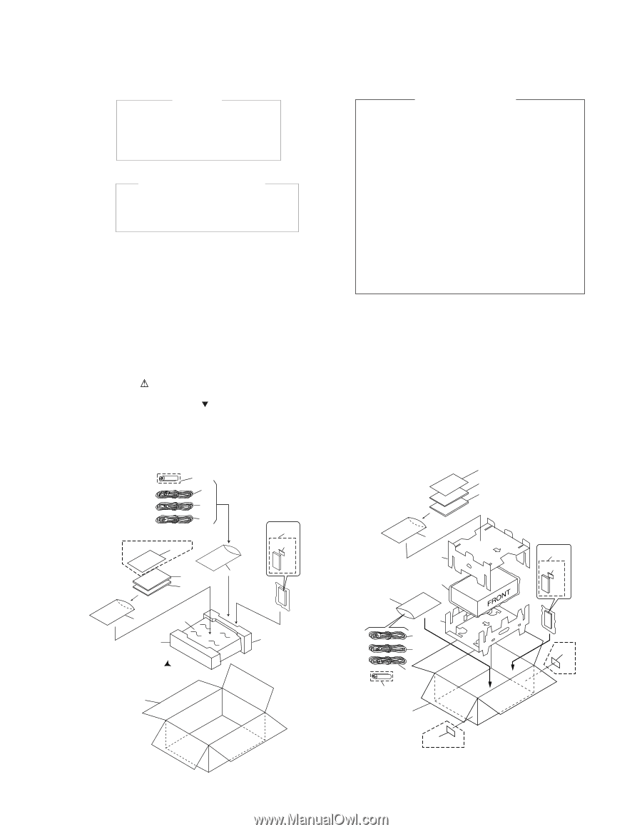
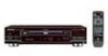
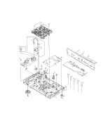
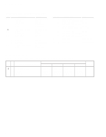
DV-515, DV-414 IMPORTANT THIS PIONNER APPARATUS CONTAINS LASER OF CLASS 1. SERVICING OPERATION OF THE APPARATUS SHOULD BE DONE BY A SPECIALLY INSTRUCTED PERSON. LASER DIODE CHARACTERISTICS FOR DVD : MAXIMUM OUTPUT POWER : 7 mw WAVELENGTH : 650 nm FOR CD : MAXIMUM OUTPUT POWER : 5mW WAVELENGTH : 780 - 785 nm Additional Laser Caution 1. Inside detection switch (S201 on the SMEB assy) and loadingstatus detection switch (S301 on the LOSB assy) are detected by the microprocessor (IC501 in the DVDM assy). • To permit the laser diode to oscillate, it is required to set the inside detection switch for the inside position (S201 : ON) and to set the loading-status detection switch for the clamp position (the center terminal of S301 is shorted to +5V). The 650 nm laser diode for DVD oscillation will continue if pin 19 of IC101 is shorted to +5V (fault condition) in the DVDM assy. The 780 nm laser diode for CD oscillates if pin 20 of IC101 is shorted to +5V in the DVDM assy. In the test mode ∗ , the laser diode oscillates when microprocessor detects a PLAY signal, or when the PLAY key is pressed (S113 ON in the FLKB assy), with the above requirements satisfied. 2. When the cover is open, close viewing through the objective lens with the naked eye will cause exposure to the laser beam. ∗ : Refer to the service guide RRV2004. 2. EXPLODED VIEWS AND PARTS LIST • NOTES: Parts marked by "NSP" are generally unavailable because they are not in our Master Spare Parts List. • The mark found on some component parts indicates the importance of the safety factor of the part. Therefore, when replacing, be sure to use parts of identical designation. • Screws adjacent to mark on the product are used for disassembly. 2.1 PACKING • For DV-515 7 5 6 1 (DV-515/RAM only) 15 4 16 3 10 8 10 14 17 18 FRONT 13 • For DV-414 4 3 8 10 11 14 10 12 1 6 5 7 13 DV-414 /KC only 19 15 16 19 DV-414 /KC only 3
-
 1
1 -
 2
2 -
 3
3 -
 4
4 -
 5
5 -
 6
6 -
 7
7 -
 8
8 -
 9
9 -
10
-
11
-
12
-
13
-
14
-
15
-
16
-
17
-
18
-
19
-
20
-
21
-
22
-
23
-
24
-
25
-
26
-
27
-
28
-
29
-
30
-
31
-
32
-
33
-
34
-
35
-
36
-
37
-
38
-
39
-
40
-
41
-
42
-
43
-
44
-
45
-
46
-
47
-
48
-
49
-
50
-
51
-
52
-
53
-
54
-
55
-
56
-
57
-
58
-
59
 |
 |