Pioneer FH-P4200MP Other Manual
Pioneer FH-P4200MP - Radio / CD Manual
 |
UPC - 012562728421
View all Pioneer FH-P4200MP manuals
Add to My Manuals
Save this manual to your list of manuals |
Pioneer FH-P4200MP manual content summary:
- Pioneer FH-P4200MP | Other Manual - Page 1
If not, keep the Audio Mute lead free of any connections. Fuse IP-BUS cable Multi-CD player (sold separately) Blue/white To system control terminal of the power amp or Auto-antenna relay control terminal (max. 300 mA 12 V DC). + Front speaker ≠ System remote control + Front speaker ≠ Yellow To - Pioneer FH-P4200MP | Other Manual - Page 2
: • Before making a final installation of the unit, tem- porarily connect the wiring to confirm that the connections are correct and the system works properly. • Use only the parts included with the unit to ensure proper installation. The use of unauthorized parts can cause malfunctions. • Consult - Pioneer FH-P4200MP | Other Manual - Page 3
aux véhicules avec une batterie de 12 V, avec pôle négatif à la masse. Avant de l'installer dans un véhicule de loisir, un camion ou un car cet appareil doivent être en mesure de supporter une puissance de 50 W, et doivent pr . Fusible Câble IP-BUS Lecteur de CD à chargeur (vendu séparément) Bleu - Pioneer FH-P4200MP | Other Manual - Page 4
les trous de vis sur les côtés de l'appareil Fixation de l'appareil au support pour le montage de la radio installée par le constructeur. (Fig. 4) (Fig. 5) Choisir la position selon laquelle les orifices de vis du support et ceux des vis de l'appareil principal sont alignés (correspondent) et serrer
-
 1
1 -
 2
2 -
 3
3 -
 4
4
 |
 |

+
≠
+
≠
+
≠
+
≠
+
≠
+
≠
+
≠
+
≠
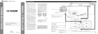
Subwoofer output or nonfading output
This Product
IP-BUS cable
Connecting cords
with RCA pin plugs
(sold separately)
Subwoofer or
Rear speaker
Subwoofer or
Rear speaker
Right
Front speaker
Rear speaker
White
Gray
White/black
Green
Green/black
Gray/black
Violet
Violet/black
Front speaker
Rear speaker
Left
Front speaker
Front speaker
With a 2 speaker system, do not connect
anything to the speaker leads that are not
connected to speakers.
Yellow
To terminal always supplied
with power regardless of
ignition switch position.
Orange/white
To lighting switch terminal.
Red
To electric terminal controlled by
ignition switch (12 V DC) ON/OFF.
Black (ground)
To vehicle (metal) body.
This terminal may or
may not be included.
Antenna jack
Blue/white
To system control terminal of the power amp
or Auto-antenna relay control terminal
(max. 300 mA 12 V DC).
IP-BUS input (Blue)
System remote control
am
Power
p
(sold separately)
Fuse
Front output
(FRONT OUTPUT)
15 cm (5-7/8 in.)
Multi-CD player
(sold separately)
Power amp
(sold separately)
Perform these connections when using
the optional amplifier.
Yellow/black
If you use an equipment with Mute function, wire this lead
to the Audio Mute lead on that equipment. If not, keep the
Audio Mute lead free of any connections.
Fig. 2
Note:
•
This unit is for vehicles with a 12-volt battery and
negative grounding. Before installing it in a recre-
ational vehicle, truck or bus, check the battery
voltage.
•
To avoid shorts in the electrical system, be sure to
disconnect the
≠
battery cable before beginning
installation.
•
Refer to the owner’s manual for details on
connecting the power amp and other units, then
make connections correctly.
•
Secure the wiring with cable clamps or adhesive
tape. To protect the wiring, wrap adhesive tape
around them where they lie against metal parts.
•
Route and secure all wiring so it cannot touch any
moving parts, such as the gear shift, handbrake,
and seat rails. Do not route wiring in places that
get hot, such as near the heater outlet. If the insu-
lation of the wiring melts or gets torn, there is a
danger of the wiring short-circuiting to the vehicle
body.
•
Don’t pass the yellow lead through a hole into the
engine compartment to connect to the battery.
This will damage the lead insulation and cause a
very dangerous short.
•
Do not shorten any leads. If you do, the protection
circuit may fail to work when it should.
•
Never feed power to other equipment by cutting
the insulation of the power supply lead of the unit
and tapping into the lead. The current capacity of
the lead will be exceeded, causing overheating.
•
When replacing the fuse, be sure to only use a
fuse of the rating prescribed on this unit.
•
Since a unique BPTL circuit is employed, never
wire so the speaker leads are directly grounded or
the left and right
≠
speaker leads are common.
•
If the RCA pin jack on the unit will not be used,
do not remove the caps attached to the end of the
connector.
•
Speakers connected to this unit must be high-
power with minimum rating of 50 W and imped-
ance of 4 to 8 ohms. Connecting speakers with
output and/or impedance values other than those
noted here may result in the speakers catching
fire, emitting smoke or becoming damaged.
•
When this product’s source is switched ON, a
control signal is output through the blue/white
lead. Connect to an external power amp’s system
remote control or the car’s Auto-antenna relay
control terminal (max. 300 mA 12 V DC). If the
car features a glass antenna, connect to the anten-
na booster power supply terminal.
•
When an external power amp is being used with
this system, be sure not to connect the blue/white
lead to the amp’s power terminal. Likewise, do
not connect the blue/white lead to the power ter-
minal of the auto-antenna. Such connection could
cause excessive current drain and malfunction.
•
To avoid a short-circuit, cover the disconnected
lead with insulating tape. Insulate the unused
speaker leads without fail. There is a possibility of
a short-circuit if the leads are not insulated.
•
To prevent incorrect connection, the input side of
the IP-BUS connector is blue, and the output side
is black. Connect the connectors of the same
colors correctly.
•
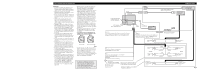
This unit can not be installed in a vehicle that
does not have an ACC (accessory) position on
the ignition switch. (Fig. 1)
Fig. 1
•
The black lead is ground. Please ground this lead
separately from the ground of high-current prod-
ucts such as power amps.
If you ground the products together and the
ground becomes detached, there is a risk of dam-
age to the products or fire.
No ACC position
ACC position
O
N
S
T
A
R
T
O
F
F
A
C
C
O
N
S
T
A
R
T
O
F
F
Connecting the Units
<ENGLISH>
INSTALLATION MANUAL
MANUEL D’INSTALLATION
This product conforms to CEMA cord colors.
Le code de couleur des câbles utilisé pour ce produit
est conforme à CEMA.
<KMINX> <04J00001>
Printed in China
Imprimé en Chine
<YRD5034-A/U> UC
FH-P4200MP
•
Cords for this product and those for other prod-
ucts may be different colors even if they have the
same function. When connecting this product to
another product, refer to the supplied manuals of
both products and connect cords that have the
same function.