Pioneer FH-P4200MP Other Manual - Page 2
Installation, <ENGLISH> - parts
 |
UPC - 012562728421
View all Pioneer FH-P4200MP manuals
Add to My Manuals
Save this manual to your list of manuals |
Page 2 highlights
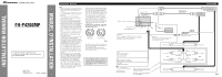
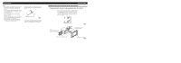
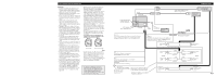
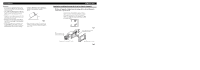
Installation Note: • Before making a final installation of the unit, tem- porarily connect the wiring to confirm that the connections are correct and the system works properly. • Use only the parts included with the unit to ensure proper installation. The use of unauthorized parts can cause malfunctions. • Consult with your nearest dealer if installation requires the drilling of holes or other modifications of the vehicle. • Install the unit where it does not get in the driver's way and cannot injure the passenger if there is a sudden stop, like an emergency stop. • The semiconductor laser will be damaged if it overheats, so don't install the unit anywhere hot - for instance, near a heater outlet. • If installation angle exceeds 30° from horizontal, the unit might not give its optimum performance. (Fig. 3) 30˚ Fig. 3 • In some types of automobiles, discrepancy may occur between this unit and the dashboard. If this happens, use the supplied panel to fill the gap. Installation using the screw holes on the side of the unit Fastening the unit to the factory radio mounting bracket. (Fig. 4) (Fig. 5) Select a position where the screw holes of the bracket and the screw holes of the head unit become aligned (are fitted), and tighten the screws at 3 or 4 places on each side. Use either binding screws (5 × 8 mm) or flush surface screws (5 × 8 mm), depending on the shape of the screw holes in the bracket. Screw Be sure to use the screws supplied with this product. Factory radio mounting bracket Fig. 4 If the pawl gets in the way, bend it down. Dashboard or Console Fig. 5
-
 1
1 -
 2
2 -
 3
3 -
 4
4
 |
 |
