Pioneer GM-X432 Service Manual - Page 17
Connecting the Unit
 |
View all Pioneer GM-X432 manuals
Add to My Manuals
Save this manual to your list of manuals |
Page 17 highlights
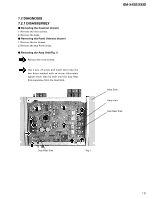
GM-X432,X332 17 Connecting the Unit CAUTION • Remove the negative (-) terminal of the battery to avoid the risk of short-circuit and damage to the unit. • Secure the wiring with cable clamps or adhesive tape. To protect the wiring, wrap adhesive tape around them where they lie against metal parts. • Do not route wires where they will get hot, for example where the heater will blow over them. If the insulation heats up, it may become damaged, resulting in a short-circuit through the vehicle body. • Make sure that wires will not interfere with moving parts of the vehicle, such as the gearshift, handbrake or seat sliding mechanism. • Do not shorten any wires. Otherwise the protection circuit may fail to work when it should. • Never feed power to other equipment by cutting the insulation of the power supply wire to tap from the wire. The current capacity of the wire will be exceeded, causing overheating. To prevent damage • Do not ground the speaker wire directly or connect a negative (-) lead wire for several speakers. • This unit is for vehicles with a 12-volt battery and negative grounding. Before installing it in a recreational vehicle, truck, or bus, check the battery voltage. • If the car stereo is kept on for a long time while the engine is at rest or idling, the battery may go dead. Turn the car stereo off when the engine is at rest or idling. • If the system remote control wire of the amplifier is connected to the power terminal through the ignition switch (12 V DC), the amplifier will always be on when the ignition is on- regardless of whether the car stereo is on or off. Because of this, the battery could go dead if the engine is at rest or idle. • Install and route the sold separately battery wire as far away as possible from the speaker wires. Install and route the sold separately battery wire and ground wire, speaker wires, and the amplifier as far away as possible from the antenna, antenna cable and tuner. • Speakers to be connected to the amplifier should conform with the standards listed below. Otherwise damage will occur to the speaker. The speaker impedance must be 1 to 8 ohms. (2 to 8 Ω for stereo, monaural and other bridge connections.) Speaker Channel Two-channel One-channel Speaker Type Sub-woofer Other than sub-woofer Sub-woofer Other than sub-woofer Power Nominal input: Min. 35 W Max. input: Min. 70 W Nominal input: Min. 100 W Max. input: Min. 200 W Connection Diagram Grommet Fuse (30 A) Special red battery wire [RD-222] (sold separately). After making all other connections at the amplifier, connect the battery wire terminal of the amplifier to the positive (+) terminal of the battery. Ground wire (black) [RD-222] (sold separately). Connect to metal body or chassis. RCA input (sold separately) Connecting wires with RCA pin plugs (sold separately). Amplifier with RCA input jacks Car stereo with RCA output jacks External Output RCA output jack RCA input jack Fuse (20 A) Speaker terminal See the "Connecting the Speaker wires" section for speaker connection instructions. System remote control wire (sold separately) Connect the male terminal of this wire to the system remote control terminal of the car stereo (SYSTEM REMOTE CONTROL). The female terminal can be connected to the auto-antenna relay control terminal. If the car stereo does not have a system remote control terminal, connect the male terminal to the power terminal through the ignition switch.
-
 1
1 -
2
-
3
-
4
-
5
-
6
-
7
-
8
-
9
-
10
-
11
-
 12
12 -
 13
13 -
 14
14 -
 15
15 -
 16
16 -
 17
17 -
 18
18
 |
 |
