Pioneer IS-21MD Service Manual - Page 17
General Information
 |
View all Pioneer IS-21MD manuals
Add to My Manuals
Save this manual to your list of manuals |
Page 17 highlights
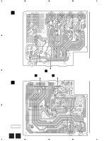
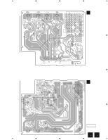
M-IS21 7. GENERAL INFORMATION 7.1 SINGLE OPERATION METHOD Single operation method and inputlevel. The procedure and the input level of a single operation are shown below. 1. R85 are shorted by 1kΩ. 2. A point of the figure below in four places is connected. GND is not common because it is independent with chassis GND (GND of the amplifier), B1GND, B2GND, and B3GND. The potential of B1GND, B2GND, and B3GND is done by connecting A point in four places as well as chassis GND. 2. The power supply of the product is turned on. 3. the terminal CONT (2 pin of CN3332) are controlled respectively by the following voltages. RY MUTE 12V ON OFF CONT 5V ON ON 0V OFF ON 4. The signal of 10mV is input from input terminal (JA3333), and the output is confirmed with speaker terminal (CN3331). Note : If the music signal is input directly to input terminal (JA3333) with CD PLAYER etc. , the output becomes a large volume because there are 40dB GAIN of the amplifier. A AF ASSY CONNECT A POINT (GND) (FOUR PLACES) INPUT SIGNAL 10mV CONTROLL 0V, 5V or 12V SIDE B OUTPUT SIGNAL R85 - 1kΩ Caution when disassemble. Even if the power supply code is pulled out from the outlet, neither C11 nor C12 of AF ASSY are discharged. Please discharge C11 and C12 of AF ASSY by the resistor of 100 Ω or more before removing AF ASSY or POWER SUPPLY ASSY. There is a possibility to destroy the transistor, and Please discharge by the resistor of 100 Ω or more. 17
-
 1
1 -
2
-
3
-
4
-
5
-
6
-
7
-
8
-
9
-
10
-
11
-
 12
12 -
 13
13 -
 14
14 -
 15
15 -
 16
16 -
 17
17 -
 18
18
 |
 |
