Pioneer MVH-P8200BT Installation Manual
Pioneer MVH-P8200BT Manual
 |
UPC - 012562976075
View all Pioneer MVH-P8200BT manuals
Add to My Manuals
Save this manual to your list of manuals |
Pioneer MVH-P8200BT manual content summary:
- Pioneer MVH-P8200BT | Installation Manual - Page 1
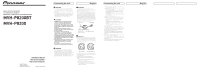
MEDIA CENTER RECEIVER AUTORADIO MULTIMEDIA RECEPTOR Y CENTRO DE COMUNICACIONES MVH-P8200BT MVH-P8200 Installation Manual Manuel d'installation Manual de instalación Printed in Thailand Imprimé en Thaïlande UC Connecting the unit English WARNING • To avoid the - Pioneer MVH-P8200BT | Installation Manual - Page 2
dangers. Confiez tous les travaux d'installation et d'entretien de votre écran à un personnel de service Pioneer agréé. • Immobilisez toutes les câ assurez-vous de suivre les instructions ci-dessous. - Déconnectez la borne négative de la batterie avant l'installation. - Fixez solidement les câbles - Pioneer MVH-P8200BT | Installation Manual - Page 3
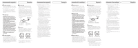
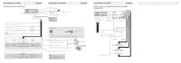
(MVH-P8200BT only) Wired remote input Hard-wired remote control adaptor can be connected (sold separately). Pioneer IP-BUS accessories (sold separately) English Connection method 1. Clamp the lead. 2. Clamp firmly with needle-nosed pliers. Note: · The position of the parking brake switch - Pioneer MVH-P8200BT | Installation Manual - Page 4
Ω) × 2 � Connexions des appareils Entrée microphone (MVH-P8200BT seulement) Microphone 4 m (MVH-P8200BT seulement) Entrée de télécommande à fil Vous pouvez connecter un adaptateur pour télécommande à fil (vendu séparément) à cette prise. Accessoire Pioneer IP-BUS (vendu séparément) Français - Pioneer MVH-P8200BT | Installation Manual - Page 5
MVH-P8200BT) Micrófono 4 m (solamente MVH-P8200BT) Entrada remota por cable Es posible conectar un adaptador de control remoto por cable (vendido separadamente). Accesorios IP-BUS Pioneer el ajuste inicial de esta unidad (refiérase al manual de operación). La salida de altavoz de subgraves de - Pioneer MVH-P8200BT | Installation Manual - Page 6
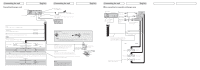
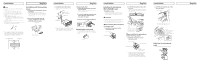
10cm (3-7/8 in.) Mounting sleeve 10cm (3-7/8 in.) Installation 3. Install the unit as illustrated. • Use commercially available parts when installing. Nut Firewall or metal support Screw Metal strap Screw (M4™8) English Removing the Unit 1. Press the detach button to release the front panel - Pioneer MVH-P8200BT | Installation Manual - Page 7
des pièces disponibles dans le commerce lors de l'installation. Écrou Pare-feu ou support métallique Attache en métal Vis Vis (M4™8) avec la vis fournie. Vis Installation Français Installation du microphone (MVH-P8200BT seulement) Remarques sur l'installation Installez et orientez le microphone - Pioneer MVH-P8200BT | Installation Manual - Page 8
botón de liberación para liberar el panel delantero. • Consulte el Manual de instrucciones para saber cómo liberar el panel delantero. 2. Inserte las Tornillo Instalación Instalación del micróphono (solamente MVH-P8200BT) Notas acerca de la instalación Instale el micrófono en una posición u
-
 1
1 -
 2
2 -
 3
3 -
 4
4 -
 5
5 -
 6
6 -
 7
7 -
8
 |
 |

MEDIA CENTER RECEIVER
AUTORADIO MULTIMEDIA
RECEPTOR Y CENTRO DE COMUNICACIONES
MVH-P8200BT
MVH-P8200
Connecting the unit
English
WARNING
• To avoid the risk of accident and the potential
violation of applicable laws, no viewing of front
seat video should ever occur while the vehicle is
being driven.
• In some countries or states the viewing of images
on a display inside a vehicle even by persons
other than the driver may be illegal. Where such
regulations apply, they must be obeyed.
CAUTION
• PIONEER does not recommend that you
install or service your display yourself.
Installing or servicing the product may
expose you to risk of electric shock or other
hazards. Refer all installation and servicing
of your display to authorized Pioneer service
personnel.
• Secure all wiring with cable clamps or
electrical tape. Do not allow any bare wiring
to remain exposed.
• Do not drill a hole into the engine
compartment to connect the yellow lead
of the unit to the vehicle battery. Engine
vibration may eventually cause the insulation
to fail at the point where the wire passes from
the passenger compartment into the engine
compartment. Take extra care in securing the
wire at this point.
• Make sure that wires will not interfere with
moving parts of the vehicle, such as the
gearshift, parking brake or seat sliding
mechanism.
• Do not shorten any leads. If you do, the
protection circuit may fail to work properly.
WARNING
LIGHT GREEN LEAD AT POWER CONNECTOR
IS DESIGNED TO DETECT PARKED STATUS
AND MUST BE CONNECTED TO THE POWER
SUPPLY SIDE OF THE PARKING BRAKE SWITCH.
IMPROPER CONNECTION OR USE OF THIS
LEAD MAY VIOLATE APPLICABLE LAW AND MAY
RESULT IN SERIOUS INJURY OR DAMAGE.
WARNING
• Use speakers over 50 W (output value) and
between 4
W
to 8
W
(impedance value). Do not use
1
W
to 3
W
speakers for this unit.
• The black cable is ground. When installing this
unit or power amp (sold separately), make sure
to connect the ground wire first. Ensure that
the ground wire is properly connected to metal
parts of the car’s body. The ground wire of the
power amp and the one of this unit or any other
device must be connected to the car separately
with different screws. If the screw for the ground
wire loosens or falls out, it could result in fire,
generation of smoke or malfunction.
Ground wire
Metal parts of car’s body
Other devices
(Another electronic
device in the car)
POWER AMP
Important
• When this unit is installed in a vehicle without
ACC (accessory) position on the ignition switch,
red cable must be wired to the terminal that can
detect the operation of the ignition key. Otherwise,
battery drain may result.
A
C
C
O
N
S
T
A
R
T
O
F
F
O
N
S
T
A
R
T
O
F
F
ACC position
No ACC position
• Use this unit with a 12-volt battery and negative
grounding only. Failure to do so may result in a
fire or malfunction.
• To prevent short-circuit, overheating or
malfunction, be sure to follow the directions
below.
— Disconnect the negative terminal of the
battery before installation.
— Secure the wiring with cable clamps or
adhesive tape. To protect the wiring, wrap
adhesive tape around them where they lie
against metal parts.
Installation Manual
Manuel d’installation
Manual de instalación
<KOKNX> <09L00000>
Printed in Thailand
Imprimé en Thaïlande
<
CRD4472-A/N
> UC
Connecting the unit
English
— Place all cables away from moving parts, such
as gear shift and seat rails.
— Place all cables away from hot places, such as
near the heater outlet.
— Do not connect the yellow cable to the battery
by passing it through the hole to the engine
compartment.
— Cover any disconnected cable connectors with
insulating tape.
— Do not shorten any cables.
— Never cut the insulation of the power cable of
this unit in order to share the power to other
equipment. Current capacity of the cable is
limited.
— Use a fuse of the rating prescribed.
— Never wire the speaker negative cable directly
to ground.
— Never band together multiple speaker’s
negative cables.
• When this unit is on, control signals are sent
through the blue/white cable. Connect this cable
to the system remote control of an external power
amp or the vehicle’s auto-antenna relay control
terminal (max. 300 mA 12 V DC).
If the vehicle is equipped with a glass antenna,
connect it to the antenna booster power supply
terminal.
• Never connect the blue/white cable to the power
terminal of an external power amp.
Also, never connect it to the power terminal of the
auto antenna. Doing so may result in battery drain
or a malfunction.
• IP-BUS connectors are color-coded. Be sure to
connect connectors of the same color.