Pioneer PD-F1007 Service Manual
Pioneer PD-F1007 Manual
 |
View all Pioneer PD-F1007 manuals
Add to My Manuals
Save this manual to your list of manuals |
Pioneer PD-F1007 manual content summary:
- Pioneer PD-F1007 | Service Manual - Page 1
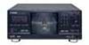
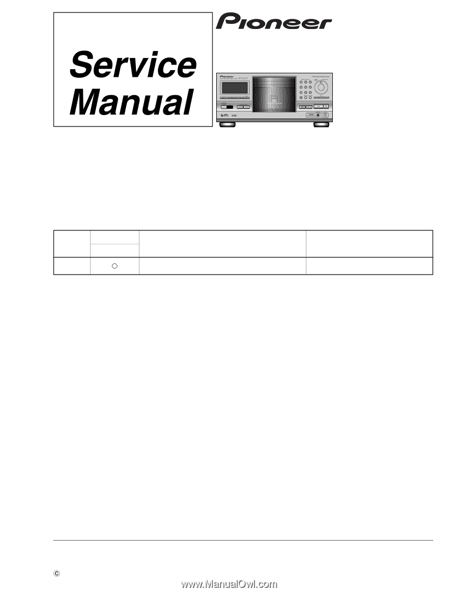
FILE-TYPE CD PLAYER PD-F1007 ORDER NO. RRV2001 THIS MANUAL IS APPLICABLE TO THE FOLLOWING MODEL(S) AND TYPE(S). Type Model PD-F1007 Power Requirement Remarks KU AC120V CONTENTS 1. SAFETY INFORMATION 2 2. EXPLODED VIEWS AND PARTS LIST 3 3. SCHEMATIC DIAGRAM 10 4. PCB CONNECTION DIAGRAM - Pioneer PD-F1007 | Service Manual - Page 2
or other hazards. Product Safety is continuously under review and new instructions are issued from time to time. For the latest information, always consult the current PIONEER Service Manual. A subscription to, or additional copies of, PIONEER Service Manual may be obtained at a nominal charge from - Pioneer PD-F1007 | Service Manual - Page 3
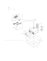
PD-F1007 2. EXPLODED VIEWS AND PARTS LIST NOTES : Parts marked by " NSP " are 6 Operating Instructions (English) PRB1271 7 Remote Control Unit PWW1139 (CD-PD094) 3 8 Battery Cover AZA7204 NSP 9 Dry Cell Batteries (R6P, AA) VEM-013 10 Control Cable (L=1 m) PDE1247 11 Audio Cable (L=1 - Pioneer PD-F1007 | Service Manual - Page 4
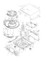
PD-F1007 8 2.2 EXTERIOR (1/2) 19 20 ∗2 22 21 14 (1/2) 6 6 F 18 3 C D E 15 Refer to " 2.3 EXTERIOR (2/2)". G H 22 2 I I A CD E FG B 23 20 20 H 22 20 20 17 6 12 Hood Base Assy 16 11 (1/2) 20 20 4 11 (2/2) 20 20 7 21 22 13 1 5 20 14 (2/2) 20 9 A - Pioneer PD-F1007 | Service Manual - Page 5
PD-F1007 No. 14: Center Pole Cut 14 (2/2) Cut 14 (1/2) No. 11: Trans Cover 11 PRW1517 BBZ30P080FZK 21 Screw 22 Screw 23 Binder FBT40P080FZK IBZ30P080FMC ZCA-SKB90BK ∗2 Ha Narl PN955R (for service) GEM1016 Mark No. Description Part No. Hood Base Assy Section NSP 24 DOOR MOTOR BOARD ASSY - Pioneer PD-F1007 | Service Manual - Page 6
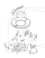
PD-F1007 2.3 EXTERIOR (2/2) 53 52 B 11 44 46 52 52 40 44 33 44 44 45 44 9 10 35 36 52 44 51 A Refer to " 2.4 FLOAT BASE - Pioneer PD-F1007 | Service Manual - Page 7
Guide R (No. 27) also at the same position.] 14 22 Note) Tightening Torque: 2 kg·cm b 51 9 17 29 10 b 49 16 13 4 a 48 a ∗1 18 31 43 3 PD-F1007 37 Disc Divider 38 Guide Support L 39 Guide Support R 40 Disc Guard PNW2837 PNW2838 PNW2839 PNW2840 PNW2841 41 Sensor Stay 42 Guide - Pioneer PD-F1007 | Service Manual - Page 8
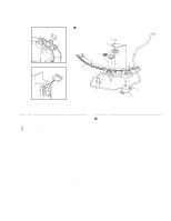
PD-F1007 2.4 DC Motor/0.3W 10 Disc Table Assy PEA1235 PEA1246 PNW2055 PXM1027 PEA1314 11 Mechanism Board Assy 12 Guide Bar 13 14 Screw Install the Disc Table 1 Use nipper or other tool to cut the three sections marked A in figure 1. Then remove the spacer 2 While supporting the spindle motor - Pioneer PD-F1007 | Service Manual - Page 9
PAC1881 PAC1882 PAC1883 PAM1776 PAM1782 Mark No. Description 11 Enter Spring 12 Jog Sheet 13 FC Cover 14 PCB Cover 15 LED Lens 16 Operation Panel 17 Sensor Lens 18 Rotary Knob 19 Screw PD-F1007 19 19 19 2 6 Part No. PBH1228 PEC1042 PNM1323 PNM1324 PNW2019 PNW2794 PNW2804 RAC1903 PPZ30P100FMC 9 - Pioneer PD-F1007 | Service Manual - Page 10
1 2 3 4 PD-F1007 3. SCHEMATIC DIAGRAM Note : When ordering service parts, be sure to refer to "EXPLODED VIEWS and PARTS LIST" or "PCB PARTS LIST". A A-a A-c A-b A-d Large size SCH diagram 3.1 MECHANISM BOARD, DOOR MOTOR BOARD, DOOR - Pioneer PD-F1007 | Service Manual - Page 11
1 2 3 4 PD-F1007 3.2 LOADING SW, LOADING BOARD, SENSOR BOARD, RECIEVE BOARD, RADIATE BOARD and SELECT BOARD ASSEMBLIES A E LOADING SW ASSY (PWZ3790) REAF SW VSK1011 G SENSOR BOARD ASSY (PWZ3781) 1. - Pioneer PD-F1007 | Service Manual - Page 12
1 2 3 4 PD-F1007 3.3 MAIN BOARD ASSY K-a CAUTION : FOR CONTINUED PROTECTION AGAINST RISK OF FIRE, REPLACE ONLY WITH SAME TYPE NO. ICP-N10, MFD BY ROHM CO., FOR IC35 AND IC36. A K MAIN BOARD ASSY (PWZ3822) -0.7V (S) 7 3 1.8V (S) 1.8V (S) 2 23 4 33 5 1.6V A CN610 (F) (F) 0V 1.6V 6 - Pioneer PD-F1007 | Service Manual - Page 13
5 6 7 8 PD-F1007 K-b IC301(CXD2529Q) :PLAY MODE PIN No. 1 2 3-4 7 8 9 10 11 12 13 14 16 17 23 24 25 Voltage(V) 5 0 0 4.7 1.2-1.3 1.2-1.4 4.4 5 4.7 4.7 0.05 5 4.7 5 5 0 PIN No. 26 27 38 39 40 - Pioneer PD-F1007 | Service Manual - Page 14
(F) (F) (F) D CAUTION : FOR CONTINUED PROTECTION AGAINST RISK OF FIRE, REPLACE ONLY WITH SAME TYPE NO. ICP-N10, MFD BY ROHM CO., FOR IC35 AND IC36. A CN610 K MAIN (C) 2 23 4 33 53 18 19 16 (T) (T) 1.7V 0V (L) 0V (L) (L) F J651 0V (SEL) (SEL) (F) C B A K-a K-b PD-F1007 4 3 2 1 - Pioneer PD-F1007 | Service Manual - Page 15
(C) : CARRIAGE SERVO LOOP (S) : SPINDLE DRIVE (L) : LOADING DRIVE (D) : DOOR DRIVE (SEL) : SELECT DRIVE J J601 (SEL) (SEL) (SEL) (F) (T) 0V 0V (D) (C) (D) (D) 0V 23 2SD2144S B J631 D J1601 O J11 L J701 B A K-a K-b PD-F1007 8 7 6 5 - Pioneer PD-F1007 | Service Manual - Page 16
Voltage(V) 5 2.6-2.7 2.5 3.1 2.5 0 3.1 5 2.5 0.9 2.5 2.5 5 2.5 0 5 PIN No. 61 71 75 78 79 82 83 84-86 87 88 89-90 91-92 93-95 96 97 100 Voltage(V) 5 2.5 0 0 5 0 5 2.5 0 5 2.5 0 2.5 5 0 5 K-a K-b N J501 A PD-F1007 4 3 2 1 - Pioneer PD-F1007 | Service Manual - Page 17
5 6 7 8 PD-F1007 K-a K-b A B C D K-b 17 5 6 7 8 - Pioneer PD-F1007 | Service Manual - Page 18
PD-F1007 Waveforms Note: The encircled numbers denote measuring point in the schematic diagram. ∗1 50T-JUMP: After switching to the pause mode, press the manual search key. ∗2 FOCUS-IN: Press the play key without loading a disc. 2 TP1-Pin 1: PLAY MODE (RF) 500mV/div 500nsec/div 4' TP1-Pin 2: 50T - Pioneer PD-F1007 | Service Manual - Page 19
PD-F1007 8 IC202-Pin 9: TRACK SEARCH MODE (CADR) 2V/div 200msec/div 16 IC301-Pin 54 : PLAY MODE (1kHz) (BCK) 2V/div 500nsec/div - GND - GND 18 - Pioneer PD-F1007 | Service Manual - Page 20
1 2 3 4 PD-F1007 3.4 DISPLAY BOARD, FUNCTION BOARD, HEADPHONE BOARD and POWER BOARD ASSEMBLIES A L DISPLAY BOARD ASSY (PWZ3839) K CN351 DISPLAY BOARD ASSY S701 : MODE S702 : CLEAR S703 : PROGRAM S704 : - Pioneer PD-F1007 | Service Manual - Page 21
ASSY (PWZ3852) K CN11 7 8 PD-F1007 A NEUTRAL To AC POWER CORD K CN401 N HEADPHONE BOARD ASSY (PWZ3860) LIVE B C M FUNCTION BOARD ASSY (PWZ3847) FUNCTION BOARD ASSY S751-S760 : DIRECT CUSTOM (1-10) S761 : Track/Manual search (reverse direction) S762 : Track/Manual search (forward direction - Pioneer PD-F1007 | Service Manual - Page 22
1 2 3 4 PD-F1007 4. PCB CONNECTION DIAGRAM A 4.1 MECHANISM BOARD, DOOR MOTOR BOARD, DOOR SW BOARD and LED BOARD ASSEMBLIES NOTE FOR PCB DIAGRAMS: 1. Part numbers in PCB diagrams match - Pioneer PD-F1007 | Service Manual - Page 23
1 2 3 4 PD-F1007 4.2 LOADING SW, LOADING BOARD, SENSOR BOARD, RECIEVE BOARD, RADIATE BOARD, SELECT BOARD and VOLUME BOARD ASSEMBLIES A F LOADING BOARD ASSY SIDE A K CN203 E LOADING SW ASSY (PNP1452-B) ( - Pioneer PD-F1007 | Service Manual - Page 24
1 2 3 4 PD-F1007 4.3 MAIN BOARD ASSY A K MAIN BOARD ASSY IC25 IC23 IC35 IC31 IC202 IC21 Q351 IC36 IC32 IC201 IC203 IC34 Q391 VR152 VR156 VR151 VR155 VR154 SIDE A Q151 VR153 B O J11 C L CN701 D 24 1 J J601 2 A CN610 3 To PICKUP ASSY 4 - Pioneer PD-F1007 | Service Manual - Page 25
5 6 Q151 VR153 Q414 Q413 Q404 Q424 Q403 Q423 7 8 PD-F1007 SIDE A A N HEADPHONE BOARD ASSY B (PNP1451-C) C (PNP1450-A) D J1601 B J631 F J651 5 6 7 D 25 8 - Pioneer PD-F1007 | Service Manual - Page 26
1 PD-F1007 A 2 3 4 SIDE B K MAIN BOARD ASSY Q470 Q471 Q451 IC406 IC408 IC407 IC405 IC401 IC341 Q426 Q425 Q405 Q415 IC301 Q152 IC B C D (PNP1450-A) 26 1 2 3 4 - Pioneer PD-F1007 | Service Manual - Page 27
5 6 7 IC301 Q152 IC331 IC151 Q406 Q416 Q382 Q363 Q381 Q362 IC352 IC351 8 PD-F1007 A SIDE B B C D 27 5 6 7 8 - Pioneer PD-F1007 | Service Manual - Page 28
1 2 3 PD-F1007 4.4 DISPLAY BOARD and FUNCTION BOARD ASSEMBLIES L DISPLAY BOARD ASSY A 4 SIDE A K CN351 B (PNP1451-C) M FUNCTION BOARD ASSY C D (PNP1451-C) 28 1 2 3 4 - Pioneer PD-F1007 | Service Manual - Page 29
1 2 3 4.5 POWER BOARD ASSY O POWER BOARD ASSY 4 PD-F1007 A SIDE A K CN11 1 2 To AC POWER CORD B LIVE NEUTRAL C (PNP1451-C) D 29 3 4 - Pioneer PD-F1007 | Service Manual - Page 30
PD-F1007 5. PCB PARTS LIST NOTES: Parts marked by "NSP" are generally unavailable because they are MECHANISM ASSY GM MECHANISM BOARD ASSY PXA1591 PWX1192 Mark No. OTHERS J603 J602 J605 Description CABLE HOLDER CABLE HOLDER 3P JUMPER WIRE 7P JUMPER WIRE 3P JUMPER WIRE Part No. 51048-0300 51048 - Pioneer PD-F1007 | Service Manual - Page 31
PD-F1007 Mark No. Description Part No. RECIEVE BOARD ASSY SEMICONDUCTORS Q621 PT381FBC OTHERS J604 CABLE HOLDER 3P JUMPER WIRE 51048-0300 CN11, CN204 9P JUMPER CONNECTOR 52147-0910 JA401, JA402 JACK JA321 OPTICAL LINK OUT CN351 CONNECTOR JA393 JACK X341 XTAL. RES. (16.9344MHz) - Pioneer PD-F1007 | Service Manual - Page 32
PD-F1007 Mark No. Description Part No. JA391, JA392, JA951, JA952 CN201 CONNECTOR 6P CN202 CKPUYF103Z25 CKPUYF104Z50 RESISTORS All Resistors RD1/4PU J OTHERS J701 CN701 CABLE HOLDER CABLE HOLDER(12P) JUMPER WIRE REMOTE RECEIVER UNIT CONNECTOR 16P 51048-1300 51063-1205 D15A12-400-2651 - Pioneer PD-F1007 | Service Manual - Page 33
. Description Part No. DOOR SW BOARD ASSY OTHERS J632 CABLE HOLDER 3P JUMPER WIRE REAF SWITCH 51048-0300 D20PDD0315E VSK1011 VOLUME ASSY SEMICONDUCTORS D1601-D1603 RESISTORS All Resistors OTHERS J1601 CABLE HOLDER JUMPER WIRE SLR-342YCT31 RD1/4PU J 51048-0300 D20PDY0325E PD-F1007 33 - Pioneer PD-F1007 | Service Manual - Page 34
PD-F1007 6. ADJUSTMENT 6.1 PREPARATIONS 6.1.1 Jigs and Measuring Instruments 8 cm DISC (With at last about 20 minutes recording) CD TEST DISC (YEDS-7) screwdriver (small) screwdriver (medium) screwdriver (large) Precise screwdriver Ball point hexagon wrench (size: 1.5mm) GGK1002 22k Low- - Pioneer PD-F1007 | Service Manual - Page 35
PD-F1007 6.2 ADJUSTMENT 6.2.1 How to Start/Cancel Test Mode TEST MODE : ON W275 W272 W275 W272 Short Point MAIN BOARD ASSY POWER Power Switch : ON Short Point MAIN BOARD ASSY TEST MODE : PLAY TEST DISC : YEDS-7 Disc Rack No.1 inwards outwards Pickup Move MODE Focus servo : CLOSE 6 - Pioneer PD-F1007 | Service Manual - Page 36
PD-F1007 6.2.3 Check and Adjustment 1. Disc-detect Circuit Adjustment GND V+B V-B JIG (Peak hold circuit) SW INPUT OUTPUT MAIN BOARD ASSY W243 V+B W342 GND W233 V-B Digital multi meter GND GND (Under Base) A - Pioneer PD-F1007 | Service Manual - Page 37
PD-F1007 Step 1: Connect all equipment as shown in the diagram. Step 2: Turn on the power of the CD player. Put the test disc in the no. 1 disc slot. Step 3: Turn the test mode on. Step 4: Press the MODE key. Step 5: Turn the VR601 on the VOLUME BOARD ASSY until the meter on - Pioneer PD-F1007 | Service Manual - Page 38
PD-F1007 2. Focus Offset Adjustment Test mode None disc VR154 MAIN BOARD ASSY START TP1 (CN201) FE 6 VC 4 MAIN BOARD ASSY Player Prove (10:1) GND DC voltage 0±50mV Oscilloscope DC Mode V: 5mV/div H: 10mSec/div 3. Grating Adjustment Test mode SPDL servo = CLOSE FOCUS servo = CLOSE TRKG servo - Pioneer PD-F1007 | Service Manual - Page 39
PD-F1007 4. Tracking Error Barance Adjustment Test mode SPDL servo = CLOSE FOCUS servo = CLOSE TRKG servo = OPEN TEST DISC Innermost circumference PLAY (1 TRK) VR155 MAIN BOARD ASSY A=B A VC B START TP1 (CN201) TE 2 VC 4 MAIN BOARD ASSY Player Low pass filter 1 39kΩ 0.001µF Probe (10:1) GND - Pioneer PD-F1007 | Service Manual - Page 40
PD-F1007 6. RF Level Adjustment Test mode SPDL servo = CLOSE FOCUS servo = CLOSE TRKG servo = CLOSE TEST DISC Innermost circumference PLAY (1 TRK) VR153 MAIN BOARD ASSY START TP1 (CN201) RF 1 VC 4 MAIN BOARD ASSY Player Prove (10:1) GND 1.2VP-P ±0.1V Oscilloscope AC Mode V: 50mV/div H: 10mSec - Pioneer PD-F1007 | Service Manual - Page 41
PD-F1007 8. RF Level Adjustment Test mode SPDL servo = CLOSE FOCUS servo = CLOSE TRKG servo = CLOSE TEST DISC Innermost circumference PLAY (1 TRK) VR153 MAIN BOARD ASSY START TP1 (CN201) RF 1 VC 4 MAIN BOARD ASSY Player Make adjustment if the value exceeds the specified range. Prove (10:1) GND - Pioneer PD-F1007 | Service Manual - Page 42
PD-F1007 10. Focus Best Adjustment Test mode SPDL servo = CLOSE FOCUS servo = CLOSE TRKG servo = CLOSE TEST DISC Innermost circumference PLAY (1 TRK) VR156 MAIN BOARD ASSY START TP1 (CN201) FE 6 RF 1 VC 4 MAIN BOARD ASSY Player GND GND MAX Adjust the RF level to maximum, with the focus error - Pioneer PD-F1007 | Service Manual - Page 43
PD-F1007 12. Focus Best Adjustment Adjust this point only if adjustment was made in item 10. Test mode SPDL servo = CLOSE FOCUS servo = CLOSE TRKG servo = CLOSE TEST DISC Innermost circumference PLAY (1 TRK) VR156 MAIN BOARD ASSY START TP1 (CN201) FE 6 RF 1 VC 4 MAIN BOARD ASSY Player GND GND - Pioneer PD-F1007 | Service Manual - Page 44
36 P03/INTP3 DCS I Serial communication timing input from the main microcomputer 37 P02/INTP2 KBCLK I Keyboard communication data clock input 38 P01/INTP0 JOG1 I JOG input 1 39 P00/INTP0/TI0 RMDT I Remote control data input 40 VSS VSS - GND 41 P74 | | Not used O OPEN 44 P71 45 P70 JOG2 - Pioneer PD-F1007 | Service Manual - Page 45
PD-F1007 PD4996A (IC351: MAIN BOARD ASSY) System Control Micro-computer Pin Function No. Symbol Name I/O Description 1 P120/RTP0 DLAT O DAC control data, latch pulse output 2 P121/RTP1 XLAT O LSI control the slave) 30 P15/ANI5 KYCON O Keyboard power supply control (H: Power ON) No. Symbol Name - Pioneer PD-F1007 | Service Manual - Page 46
PD-F1007 No. Symbol Name I/O Description 71 Vss Vss - GND 72 P56 Reset output for each LSI 91 P35/PCL TRST O CD TEXT decoder IC reset output (L: Reset) 92 P36/BUZ CLED O Center LED lighting control (H: Lit) 93 P37 PLED O Sensor output for disc detection (H: Lit) 94 P90 Not used O Output of - Pioneer PD-F1007 | Service Manual - Page 47
PD-F1007 7.1.2 DISPLAY PEL1096 (V701: DISPLAY BOARD ASSY) Vacuum Fluorescent Display Pin Assignment 98 1 Grid Assignment 1-1 2-1 3-1 4-1 5-1 Pin Connection 50 PIN NO. 9999 99 99 98 888 888 - Pioneer PD-F1007 | Service Manual - Page 48
PD-F1007 7.2 DIAGNOSIS 7.2.1 DISASSEMBLY Removal of the Servo Mechanism Assy GM 1 Remove the Bonnet. (Left and right side: ×2, rear side: ×3) 2 Remove the wires from the MAIN BOARD - Pioneer PD-F1007 | Service Manual - Page 49
the screws E (4 screws), and then remove the Disc Guard. 7 Remove the Float Base Assy and Clamp Holder. Disc Guard 6 Screw E Float Base Assy (× 4) 7 Clamp Support PD-F1007 Clamp Holder 7 Clamp Spring Front Front 8 Remove the Flexible Flat Cable and the Connector Assy (4P) from the Float - Pioneer PD-F1007 | Service Manual - Page 50
PD-F1007 Removal of the Gear Holder Assy and the Disc Rack 1 Perform the steps 1 to 6 of " Removal of the Servo Mechanism Assy GM ". 2 Remove the screws A (2 screws), and then remove the Gear Holder Assy. 3 Remove the Disc Rack. 2 Screw A (× 2) Gear Holder Assy 3 Disc Rack Removal of the Hood - Pioneer PD-F1007 | Service Manual - Page 51
During spindle stop operation During disc return During disc selection (during clamping operation at the time of 26) During setup During CDR setup operation During TOC reading During search operation on the disc During play operation During pause operation During manual search Seconds - Pioneer PD-F1007 | Service Manual - Page 52
PD-F1007 User Display Display > Contents None • When the position of the selection mechanism just before switching to disc selection operation os DCNT terminal = "L". (Normally, DCNT terminal = "H" exists when the selection mechanism is stopped, so that it can be assumed that - Pioneer PD-F1007 | Service Manual - Page 53
PD-F1007 Disc No. 217 218 219 220 221 222 223 224 225 226 227 228 229 230 231 232 233 234 DCNT DPOS Disc No. 235 236 237 238 239 240 241 242 243 244 245 246 247 248 249 250 251 252 DCNT DPOS Disc No. 253 254 255 256 257 258 259 260 - Pioneer PD-F1007 | Service Manual - Page 54
PD-F1007 7.3 BLOCK DIAGRAM PICKUP Assembly SERVO CONTROLLER IC151 CXA1782CQ DECODER + DAC IC301 CXD2519Q . . Focus Tracking M . . . . Spindle Carriage Loading Disc Select AMP IC201 IC202 LA6520 CPU DISPLAY CONTROL IC701 PD4997A LPF IC405 NJM4558D-D Buffer IC407, IC408 NJM4558D-D H.P. - Pioneer PD-F1007 | Service Manual - Page 55
PD-F1007 8. PANEL FACILITIES AND SPECIFICATIONS PANEL FACILITIES FRONT PANEL RANDOM button TIME/CHARA button DIRECT CUSTOM buttons Jog dial PROGRAM button Hood ENTER TITLE/INPUT button CLEAR button MODE button STANDBY indicator POWER switch Remote control Adjust the volume level Track/Manual - Pioneer PD-F1007 | Service Manual - Page 56
/output jacks CD-DECK SYNCHRO jack Optical digital output jack Headphone jack with volume control MASTER/SLAVE Control input/output jack SLAVE Audio input 5. Accessories ÷ Remote control unit 1 ÷ Size AA/R6P dry cell batteries 2 ÷ Audio cable 1 ÷ Control cable 1 ÷ Operating instructions 1 Note
-
 1
1 -
 2
2 -
 3
3 -
 4
4 -
 5
5 -
 6
6 -
 7
7 -
8
-
9
-
10
-
11
-
12
-
13
-
14
-
15
-
16
-
17
-
18
-
19
-
20
-
21
-
22
-
23
-
24
-
25
-
26
-
27
-
28
-
29
-
30
-
31
-
32
-
33
-
34
-
35
-
36
-
37
-
38
-
39
-
40
-
41
-
42
-
43
-
44
-
45
-
46
-
47
-
48
-
49
-
50
-
51
-
52
-
53
-
54
-
55
-
56
 |
 |
ORDER NO.
PIONEER ELECTRONIC CORPORATION
4-1, Meguro 1-Chome, Meguro-ku, Tokyo 153-8654, Japan
PIONEER ELECTRONICS SERVICE, INC.
P.O. Box 1760, Long Beach, CA 90801-1760, U.S.A.
PIONEER ELECTRONIC (EUROPE) N.V.
Haven 1087, Keetberglaan 1, 9120 Melsele, Belgium
PIONEER ELECTRONICS ASIACENTRE PTE. LTD.
501 Orchard Road, #10-00 Wheelock Place, Singapore 238880
PIONEER ELECTRONIC CORPORATION 1998
FILE-TYPE CD PLAYER
RRV2001
T–DZE
AUG.
1998
Printed in Japan
PD-F1007
1. SAFETY INFORMATION
....................................
2
2. EXPLODED VIEWS AND PARTS LIST
.............
3
3. SCHEMATIC DIAGRAM
...................................
10
4. PCB CONNECTION DIAGRAM
.......................
22
5. PCB PARTS LIST
.............................................
30
6. ADJUSTMENT
..................................................
34
CONTENTS
7. GENERAL INFORMATION
..............................
44
7.1 PARTS
.......................................................
44
7.1.1 IC
.......................................................
44
7.1.2 DISPLAY
...........................................
47
7.2 DIAGNOSIS
................................................
48
7.2.1 DISASSEMBLY
.................................
48
7.2.2 ERROR CCHECK DISPLAY
.............
51
7.2.3 EXPLANATION OF DISC
DETECTION
......................................
52
7.3 BLOCK DIAGRAM
......................................
54
8. PANEL FACILITIES AND SPECIFICATIONS
.......................................................
55
THIS MANUAL IS APPLICABLE TO THE FOLLOWING MODEL(S) AND TYPE(S).
Type
Model
PD-F1007
Power Requirement
Remarks
KU
AC120V