Poulan PP10530ES User Manual
Poulan PP10530ES Manual
 |
View all Poulan PP10530ES manuals
Add to My Manuals
Save this manual to your list of manuals |
Poulan PP10530ES manual content summary:
- Poulan PP10530ES | User Manual - Page 1
IMPORTANT MANUAL Do Not Throw Away OWNER'S MANUAL MODEL NUMBER: PP10530ES SNOW THROWER WARNING: Read the Owner's Manual and follow all Warnings and Safety Instructions. Failure to do so can result in serious injury. Always Wear Eye Protection During Operation 421064 07.03.08 CL Printed in - Poulan PP10530ES | User Manual - Page 2
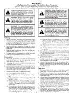
or buildings. WARNING: Snow throwers have exposed rotating parts, which can cause severe understand and follow all instructions on the machine and in the manual(s) before operating this unit gas-powered equipment Vibration is generally a warning of trouble. from the truck or trailer and refuel it - Poulan PP10530ES | User Manual - Page 3
technicians and the proper tools to service or repair this unit. Please read and retain this manual. The instructions will enable you to assemble and maintain your snow thrower properly. Always observe the "SAFETY RULES". SERIAL NUMBER DATE OF PURCHASE THE MODEL AND SERIAL NUMBERS WILL BE FOUND - Poulan PP10530ES | User Manual - Page 4
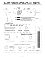
PARTS PACKED SEPARATELY IN CARTON 4 - Poulan PP10530ES | User Manual - Page 5
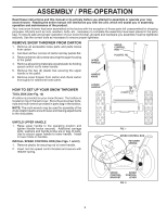
Read these instructions and this manual in its entirety before you attempt to assemble or operate your new snow thrower. Reading the entire manual will familiarize you with the unit, which will assist you in assembly, operation and maintenance of the product. Your new snow thrower has been - Poulan PP10530ES | User Manual - Page 6
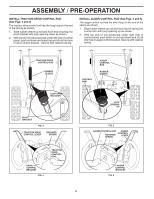
ASSEMBLY / PRE-OPERATION INSTALL TRACTION DRIVE CONTROL ROD (See Figs. 3 and 4) The traction drive control rod has the long loop on the end of the spring as shown. 1. Slide rubber sleeve up rod and hook end of spring into pivot bracket with loop opening down as shown. 2. With top end of rod - Poulan PP10530ES | User Manual - Page 7
parts bag may be used to install the chute rotater head. 1. Place discharge chute assembly on top of chute base with discharge opening toward front of snow CONTROL LEVER FIG. 9 CHECK TIRE PRESSURE The tires on your snow thrower were overinflated at the factory for shipping purposes. Correct and - Poulan PP10530ES | User Manual - Page 8
adjustments. Save this manual for future reference. These symbols may appear on your snow thrower or in literature supplied with the product. Learn and understand their meaning. DANGER OR WARNING PRIMER FORWARD REVERSE READ AND FOLLOW ALL SAFETY INFORMATION AND INSTRUCTIONS BEFORE USE OF THIS - Poulan PP10530ES | User Manual - Page 9
for starting the engine. Auger control lever - used to engage auger motion (throw Recoil (auxiliary) starter handle - used for starting engine. snow). Primer - pumps additional fuel from the carburetor to the cylinder for use when starting a cold engine. Discharge chute control lever - used to - Poulan PP10530ES | User Manual - Page 10
To engage choke, turn knob clockwise. Slowly turn knob counterclockwise to disengage. OFF FULL FIG. 13 TO CONTROL SNOW DISCHARGE (See Fig. 14) WARNING: Snow throwers have exposed rotating parts, which can cause severe injury from contact, or from material thrown from the discharge chute. Keep the - Poulan PP10530ES | User Manual - Page 11
conditions, the discharge chute may become clogged with ice and snow. Use the clean-out tool to dislodge this blockage. When cleaning, repairing, or inspecting, make certain all controls are disengaged and the auger/impeller and all moving parts have stopped. Disconnect the spark plug wire and keep - Poulan PP10530ES | User Manual - Page 12
snow thrower must be operated over gravel surface, use extra caution and be sure skid plates are adjusted to lowest (highest scraper clearance) position. 1. Shut off engine and wait for all moving parts additional service before section of this manual. ADD GASOLINE (See engine problems, Instructions - Poulan PP10530ES | User Manual - Page 13
. COLD START - RECOIL STARTER 1. Insert safety ignition key (packed separately in parts bag) into ignition slot until it clicks. DO NOT turn the key. Keep current snow conditions. See "TO ADJUST SKID PLATES" in this section of this manual. • For extremely heavy snow, reduce the width of snow removal - Poulan PP10530ES | User Manual - Page 14
snow thrower as instructed in this manual. Some adjustments will need to be made periodically to properly maintain your snow thrower. All adjustments in the Service and Adjustments section of this manual in this manual. NOTE: Use only Original Equipment Manufacturer (OEM) parts to service this unit. - Poulan PP10530ES | User Manual - Page 15
due to slow leaks, tire sealant may be purchased from your local parts dealer. Tire sealant also prevents tire dry rot and corrosion. V-BELTS Check TO REMOVE BELT COVER" in the Service and Adjustments section of this manual). The V-belts on your snow thrower are of special construction and should - Poulan PP10530ES | User Manual - Page 16
service or adjustments: 1. Be sure throttle is in STOP position. 2. Remove safety ignition key. 3. Make sure the augers and all moving parts with plug. SNOW THROWER TO ADJUST SNOW THROWER HEIGHT See "TO ADJUST SKID PLATES" and "SCRAPER BAR" in the Operation section of this manual. CHUTE DEFLECTOR - Poulan PP10530ES | User Manual - Page 17
replaced. It is recommended that the belt(s) be replaced by a qualified service center. NOTE: It is recommended that both the auger and traction drive belt chute to be removed from snow thrower. 3. REMOVE BELT COVER - See "TO REMOVE BELT COVER" in this section of this manual. 4. REMOVE ENGINE PULLEY - - Poulan PP10530ES | User Manual - Page 18
for your model snow thrower. KLIK manual. CARBURETOR Your carburetor is not adjustable. Engine performance should not be affected at altitudes up to 7,000 feet (2,134 meters). If your engine does not operate properly due to suspected carburetor problems, take your snow thrower to a qualified service - Poulan PP10530ES | User Manual - Page 19
TROUBLESHOOTING See appropriate section in manual unless directed to a qualified service center. PROBLEM FULL position. 6. Prime as instructed in the Operation section of this manual. 7. Wait a few minutes 2. Throwing too much snow. 3. Fuel tank cap is covered with ice or snow. 4. Dirty or clogged - Poulan PP10530ES | User Manual - Page 20
REPAIR PARTS SNOW THROWER - MODEL PP10530ES (96192001802) AUGER HOUSING / IMPELLER ASSEMBLY 5 11 6 15 14 13 4 12 16 11 12 3 11 1 9 10 2 11 7 8 17 33 32 34 30 31 31 29 26 28 27 35 18 25 24 23 22 21 19 01.07.004-B 36 20 21 22 23 2 (EXPLODED) 20 - Poulan PP10530ES | User Manual - Page 21
REPAIR PARTS SNOW THROWER - MODEL PP10530ES (96192001802) AUGER HOUSING / IMPELLER ASSEMBLY KEY NO. 1 2 3 4 5 6 7 8 9 10 11 12 13 14 15 16 17 18 19 20 21 22 23 24 25 26 27 28 29 30 31 32 33 34 35 36 PART NO. 175321X479 196710 188909 191079 175322 178675X008 192199 405400 73800400 74780426 155377 - Poulan PP10530ES | User Manual - Page 22
REPAIR PARTS SNOW THROWER - MODEL PP10530ES (96192001802) AUGER HOUSING / IMPELLER ASSEMBLY 1 3 (5x) 4 (5x) 2 01.07.003-A KEY NO. 1 2 3 4 PART NO. 404930X428 404933X479 72270505 155377 DESCRIPTION AUGER HOUSING SCRAPPER BAR CARRIAGE BOLT 5/16−18 X .625 NUT 5/16−18 2 3 1 1 2 3 01.07.024 - Poulan PP10530ES | User Manual - Page 23
REPAIR PARTS SNOW THROWER - MODEL PP10530ES (96192001802) AUGER HOUSING / IMPELLER ASSEMBLY 3 4 3 01.11.001-A 1 4 2 KEY NO. 1 2 3 4 PART NO. 174762X479 178777X479 72270506 751153 DESCRIPTION SKID PLATE LH SKID PLATE RH CARRIAGE BOLT 5/16−18 X .75 NUT 5/16−18 2 1 KEY NO. 1 2 PART NO. - Poulan PP10530ES | User Manual - Page 24
PARTS SNOW THROWER - MODEL PP10530ES (96192001802) CONTROL PANEL / DISCHARGE CHUTE 5 7 14 3 15 *13 KEY NO. 1 2 3 4 5 6 7 *8 *9 *10 *11 *12 *13 14 15 PART 16−18 X .50 NUT 5/16−18 DEFLECTOR SPRING (SERVICE PART) DEFLECTOR CONTROL HEAD (SERVICE PART) DEFLECTOR CONTROL CABLE *10 *9 *8 6 *12 - Poulan PP10530ES | User Manual - Page 25
PARTS SNOW THROWER - MODEL PP10530ES (96192001802) CONTROL PANEL / DISCHARGE CHUTE 2 2 *3 1 *6 *6 KEY NO. 1 2 *3 *4 *5 *6 PART 1. ITEMS INDICATED WITH AN * ARE LISTED AS REFERENCE FOR SERVICE PARTS ONLY. 2 1 KEY NO. 1 2 PART NO. 188303 74041024 01.15.005-A DESCRIPTION STEER CABLE SCREW - Poulan PP10530ES | User Manual - Page 26
REPAIR PARTS HANDLES SNOW THROWER - MODEL PP10530ES (96192001802) 5 5 4 2 3 5 5 3 KEY PART 3 NO. NO. DESCRIPTION 1 419798X479 LOOP HANDLE LH 2 419799X479 LOOP HANDLE RH 3 74780524 SCREW 5/16−18 X 1.50 4 74780528 SCREW 5/16−18 X 1.75 5 751153 NUT 5/16−18 1 - Poulan PP10530ES | User Manual - Page 27
REPAIR PARTS HANDLES SNOW THROWER - MODEL PP10530ES (96192001802) 10 2 11 9 5 7 6 8 47 9 1 3 13 8 12 13 14 14 12 01.08.002-D KEY NO. 1 2 3 4 5 6 7 8 9 10 11 12 13 14 PART NO. 412683X479 412681X479 412682X479 412679X008 420889X008 412677 412680 169675 17060408 414280 414281 178899 - Poulan PP10530ES | User Manual - Page 28
REPAIR PARTS HANDLES SNOW THROWER - MODEL PP10530ES (96192001802) 2 1 3 8 9 KEY NO. 1 2 3 4 5 6 7 8 9 10 PART NO. 180480 405740 180445 187716 180447 178669 180926 72270506 155377 169675 DESCRIPTION IMPELLER ROD ASSEMBLY TRACTION ROD ASSEMBLY SHIFTER ROD TOP SHIFTER ROD BOTTOM SPRING - Poulan PP10530ES | User Manual - Page 29
REPAIR PARTS HANDLES SNOW THROWER - MODEL PP10530ES (96192001802) 1 4 3 2 4 KEY NO. 1 2 3 4 PART NO. 419797X479 405784X479 17490508 17000616 DESCRIPTION LOWER HANDLE PIVOT SUPPORT WELDMENT SCREW 5/16−18 X .50 SCREW 3/8−16 X 1.00 3 4 4 01.05.002-A 3 2 5 6 7 4 5 41 01.10.007-B KEY NO. - Poulan PP10530ES | User Manual - Page 30
REPAIR PARTS DRIVE SNOW THROWER - MODEL PP10530ES (96192001802) 2 ITEM 43 EXPLODED 69 1 16 68 17 71 74 15 14 15 12 9 11 11 20 9 4 9 10 11 13 4 8 7 4 21 6 5 4 23 18 22 19 - Poulan PP10530ES | User Manual - Page 31
PARTS DRIVE SNOW THROWER - MODEL PP10530ES (96192001802) KEY NO. 1 2 3 4 5 6 7 8 9 10 11 12 13 14 15 16 17 18 19 20 21 22 23 24 25 26 27 28 29 30 31 32 33 34 35 36 37 38 PART SPACER TRACTION PULLEY WASHER 3/8 LOCKWASHER 3/8 LOCKWASHER BELT GUIDE IDLER ARM IDLER BRACKET IDLER PULLEY SCREW 5/16−18 - Poulan PP10530ES | User Manual - Page 32
REPAIR PARTS DRIVE SNOW THROWER - MODEL PP10530ES (96192001802) 8 1b 7 7 1b 1a 6 4 3 5 6 2 3 4 01.03.002-A KEY NO. 1 1a 1b 2 3 4 5 6 7 8 PART NO. 404923 404307 9465M1 402691 174697 179830 146315 17490508 155443 189282 DESCRIPTION AXLE ASSEMBLY (assy of 1a,1b) AXLE SHAFT ROLL PIN 3/16 X 1.50 - Poulan PP10530ES | User Manual - Page 33
REPAIR PARTS SNOW THROWER - MODEL PP10530ES (96192001802) CHASSIS / ENGINE / PULLEYS 4 2 3 4 3 1 01.00.008-A KEY NO. - - 1 2 3 4 PART NO 409346X428 417014X428 150406 150078 DESCRIPTION TECUMSEH ENGINE MODEL LH358SA-159628A FRAME ENGINE MOUNT PLATE BOLT 3/8−16 SCREW 5/16−18 X .750 NOTE: - Poulan PP10530ES | User Manual - Page 34
REPAIR PARTS SNOW THROWER - MODEL PP10530ES (96192001802) CHASSIS / ENGINE / PULLEYS 1 KEY PART NO. NO. DESCRIPTION 1 192213 BELT COVER 2 2 179157 IMPELLER PULLEY 3 419744 TRACTION BELT 4 408007 IMPELLER BELT 3 4 01.04.019-A NOTE: All component dimensions given in U.S. inches. - Poulan PP10530ES | User Manual - Page 35
REPAIR PARTS WHEELS SNOW THROWER - MODEL PP10530ES (96192001802) 2 2 17 23 43 1 17 16 20 20 16 18 inches. 1 inch = 25.4 mm IMPORTANT: Use only Original Equipment Manufacturer (O.E.M.) replacement parts. Failure to do so could be hazardous, damage your snow thrower and void your warranty. 35 - Poulan PP10530ES | User Manual - Page 36
REPAIR PARTS WHEELS SNOW THROWER - MODEL PP10530ES (96192001802) 1 2 01.15.003-A KEY PART NO. NO. DESCRIPTION 1 410293 CABLE BRACKET LH 2 410294 CABLE BRACKET RH 3 3 17060410 SCREW 1/4−20 X .625 1 2 01.06.005-A KEY NO. 1 2 PART NO. 192092X421 192093X421 DESCRIPTION WHEEL 16 X 4.80 - Poulan PP10530ES | User Manual - Page 37
REPAIR PARTS BAG OF PARTS SNOW THROWER - MODEL PP10530ES (96192001802) 3 2 4 5 8 1 7 6 9 11 10 14 13 12 01.14.003-A KEY NO. 1 2 3 4 5 6 7 8 9 10 11 12 13 14 PART NO. 198563 169675 180684 184505 179829 179246 191730 72250505 751153 73800600 19131316 198636 198638 73800400 DESCRIPTION POWER - Poulan PP10530ES | User Manual - Page 38
REPAIR PARTS DECALS SNOW THROWER - MODEL PP10530ES (96192001802) 1 2 4 9 12 6 1 3 5 10 11 KEY PART NO. NO. 1 181037 2 199302 3 181035 4 181042 5 199301 6 181033 9 415475 10 183730 11 415399 12 415398 - - 421064 - - 421065 DESCRIPTION DECAL, DANGER DECAL, POULAN, 11 HP / 30" DECAL, DANGER - Poulan PP10530ES | User Manual - Page 39
SERVICE NOTES 39 - Poulan PP10530ES | User Manual - Page 40
option, without charge for parts or labor incurred in replacing parts, any part which we find to be and maintained in accordance with the instructions furnished. This Warranty does not apply Service Department 1030 Stevens Creek Road Augusta, GA 30907 USA In Canada contact: Poulan, Customer Service
-
 1
1 -
 2
2 -
 3
3 -
 4
4 -
 5
5 -
 6
6 -
 7
7 -
8
-
9
-
10
-
11
-
12
-
13
-
14
-
15
-
16
-
17
-
18
-
19
-
20
-
21
-
22
-
23
-
24
-
25
-
26
-
27
-
28
-
29
-
30
-
31
-
32
-
33
-
34
-
35
-
36
-
37
-
38
-
39
-
40
 |
 |
OWNER'S MANUAL
MODEL NUMBER:
PP10530ES
SNOW THROWER
Always Wear Eye Protection During Operation
IMPORTANT MANUAL
Do Not Throw Away
WARNING:
Read the Owner's Manual and
follow all Warnings and Safety
Instructions.
Failure to do so
can result in serious injury.
421064
07.03.08
CL
Printed in U.S.A.