Poulan XT1053ES User Manual
Poulan XT1053ES Manual
 |
View all Poulan XT1053ES manuals
Add to My Manuals
Save this manual to your list of manuals |
Poulan XT1053ES manual content summary:
- Poulan XT1053ES | User Manual - Page 1
IMPORTANT MANUAL Do Not Throw Away OWNER'S MANUAL MODEL NUMBER: XT1053ES SNOW THROWER WARNING: Read the Owner's Manual and follow all Warnings and Safety Instructions. Failure to do so can result in serious injury. Always Wear Eye Protection During Operation 422088 10.02.08 SR Printed in the - Poulan XT1053ES | User Manual - Page 2
startup. CAUTION: Muffler and other engine parts become extremely hot during operation and remain understand and follow all instructions on the machine and in the manual(s) before operating this powered equipment Vibration is generally a warning of trouble. from the truck or trailer and refuel - Poulan XT1053ES | User Manual - Page 3
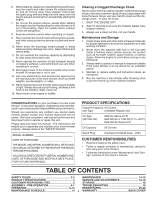
moving parts instructions under "Maintenance" and "Storage" sections of this owner's manual. TABLE OF CONTENTS SAFETY RULES 2-3 MAINTENANCE 14-15 PRODUCT SPECIFICATIONS 3 SERVICE AND ADJUSTMENTS 16-18 CUSTOMER RESPONSIBILITIES 3 STORAGE 18 ASSEMBLY / PRE-OPERATION 4-7 TROUBLESHOOTING - Poulan XT1053ES | User Manual - Page 4
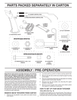
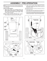
LOCKNUTS 1/4-20 (73800400) ASSEMBLY / PRE-OPERATION Read these instructions and this manual in its entirety before you attempt to assemble or operate . 6. Remove snow thrower from carton and check carton thoroughly for additional loose parts. HOW TO SET UP YOUR SNOW THROWER TOOL BOX (See Fig. 10) - Poulan XT1053ES | User Manual - Page 5
1. Raise upper handle to the operating position and tighten handle knobs securely. Additional carriage bolts, washers and handle knobs are in bag of parts. Use to secure upper handle to lower handle. Install in lower holes in handles. INSTALL SPEED CONTROL ROD (See Figs. 1 and 2) 1. Remove plastic - Poulan XT1053ES | User Manual - Page 6
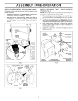
spring. CONTROL ARM AUGER CONTROL ROD RUBBER SLEEVE INSTALL DISCHARGE CHUTE / CHUTE ROTATER HEAD (See Fig. 7) NOTE: The multi-wrench provided in your parts bag may be used to install the chute rotater head. 1. Place discharge chute assembly on top of chute base with discharge opening toward front - Poulan XT1053ES | User Manual - Page 7
ASSEMBLY / PRE-OPERATION INSTALL CHUTE DEFLECTOR REMOTE CONTROL (See Figs. 8 and 9) 1. Install remote cable bracket to discharge chute with 5/16-18 carriage bolt and 5/16-18 locknut as shown. Tighten securely. 2. Install remote cable eyelet to chute deflector with 1/4-20 shoulder bolt, nylon washer - Poulan XT1053ES | User Manual - Page 8
yourself with the location of various controls and adjustments. Save this manual for future reference. These symbols may appear on your snow READ AND FOLLOW ALL SAFETY INFORMATION AND INSTRUCTIONS BEFORE USE OF THIS PRODUCT. KEEP THESE INSTRUCTIONS FOR FUTURE REFERENCE. IGNITION KEY. INSERT - Poulan XT1053ES | User Manual - Page 9
OPERATION SAFETY IGNITION KEY SPARK PLUG CHOKE CONTROL THROTTLE / ENGINE CONTROL ENGINE OIL CAP AUGER DISCHARGE CHUTE CONTROL LEVER WITH DIPSTICK CONTROL LEVER GASOLINE DRIVE SPEED CONTROL LEVER DEFLECTOR REMOTE CONTROL LEVER FILLER CAP CHUTE DEFLECTOR FUEL SHUT-OFF VALVE TRACTION - Poulan XT1053ES | User Manual - Page 10
SNOW DISCHARGE (See Fig. 14) WARNING: Snow throwers have exposed rotating parts, which can cause severe injury from contact, or from material thrown from chute or auger become clogged, shut-off engine and wait for all moving parts to stop. Use the clean-out tool, NOT YOUR HANDS, to unclog the - Poulan XT1053ES | User Manual - Page 11
tool to dislodge this blockage. When cleaning, repairing, or inspecting, make certain all controls are disengaged and the auger/impeller and all moving parts have stopped. Disconnect the spark plug wire and keep the wire away from the spark plug to prevent accidental starting. • Release the auger - Poulan XT1053ES | User Manual - Page 12
and wait for all moving parts to stop. 2. Adjust " in the Maintenance section of this manual. ADD GASOLINE (See Fig. 20) • storage. To avoid engine problems, the fuel system should season. See Storage Instructions for additional information , providing additional service before requiring replacement - Poulan XT1053ES | User Manual - Page 13
COLD START - ELECTRIC STARTER 1. Insert safety ignition key (packed separately in parts bag) into ignition slot until it clicks. DO NOT turn the key. snow conditions. See "TO ADJUST SKID PLATES" in this section of this manual. • For extremely heavy snow, reduce the width of snow removal by - Poulan XT1053ES | User Manual - Page 14
operator must maintain snow thrower as instructed in this manual. Some adjustments will need to be maintenance schedule in this manual. NOTE: Use only Original Equipment Manufacturer (OEM) parts to service this unit. Failure to parts dealer. Tire sealant also prevents tire dry rot and corrosion. 14 - Poulan XT1053ES | User Manual - Page 15
manual). The belts on your snow thrower are of special construction and should be replaced by original equipment manufacturer (OEM) belts available from your nearest dealer axle (See "TO REMOVE WHEELS" in the Service and Adjustments section of this manual). 7. Remove oil fill cap/dipstick. Be careful - Poulan XT1053ES | User Manual - Page 16
service or adjustments: 1. Be sure throttle is in STOP position. 2. Remove safety ignition key. 3. Make sure the augers and all moving parts is discharged, see "TO CONTROL SNOW DISCHARGE" in the Operation section of this manual. SHEAR BOLTS (See Fig. 21) AUGER SHEAR BOLTS Both right and left-hand - Poulan XT1053ES | User Manual - Page 17
should be replaced. It is recommended that the belt(s) be replaced by a service centre/department. NOTE: It is recommended that both the auger and traction drive COVER - See "TO REMOVE BELT COVER" in this section of this manual. 4. REMOVE ENGINE PULLEY - Remove bolt, lockwasher and flat washer - Poulan XT1053ES | User Manual - Page 18
punctures or prevent flat tires due to slow leaks, tire sealant may be purchased from your local parts dealer. Tire sealant also prevents tire dry rot and corrosion. ENGINE See engine manual. CARBURETOR Your carburetor is not adjustable. Engine performance should not be affected at altitudes up to - Poulan XT1053ES | User Manual - Page 19
TROUBLESHOOTING See appropriate section in manual unless directed to an authorized service centre/department. PROBLEM CAUSE CORRECTION FAST position 5. Move to FULL position. 6. Prime as instructed in the Operation section of this manual. 7. Wait a few minutes before restarting, DO NOT prime - Poulan XT1053ES | User Manual - Page 20
REPAIR PARTS SNOW THROWER - - MODEL NUMBER XT1053ES (96192002402) AUGER HOUSING / IMPELLER ASSEMBLY 5 11 6 15 14 13 4 = 25.4 mm IMPORTANT: Use only Original Equipment Manufacturer (O.E.M.) replacement parts. Failure to do so could be hazardous, damage your snow thrower and void your warranty. 20 - Poulan XT1053ES | User Manual - Page 21
SNOW THROWER - - MODEL NUMBER XT1053ES (96192002402) AUGER HOUSING / IMPELLER ASSEMBLY KEY NO. 1 2 3 4 5 6 7 8 9 10 11 12 13 14 15 16 17 18 19 20 21 22 23 24 25 26 27 28 29 30 31 32 33 34 35 36 PART NO. DESCRIPTION 175321X479 196710 188909 191079 175322 178675X008 192199 405400 73800400 74780426 - Poulan XT1053ES | User Manual - Page 22
- - MODEL NUMBER XT1053ES (96192002402) AUGER HOUSING / IMPELLER ASSEMBLY 1 3 (5x) 4 (5x) 2 01.07.003-A KEY NO. 1 2 3 4 PART NO. 404930X505 404933X479 72270505 155377 DESCRIPTION AUGER HOUSING SCRAPER BAR CARRIAGE BOLT 5/16−18 X .625 NUT 5/16−18 2 3 1 1 2 KEY PART NO. NO. DESCRIPTION - Poulan XT1053ES | User Manual - Page 23
SNOW THROWER - - MODEL NUMBER XT1053ES (96192002402) AUGER HOUSING / IMPELLER ASSEMBLY 2 1 KEY NO. 1 2 PART NO. 420497X479 420498X479 DESCRIPTION AUGER ASSEMBLY 30 LH AUGER ASSEMBLY 30 RH 01.07.019-A 3 4 2 4 KEY PART NO. NO. DESCRIPTION 1 174762X479 SKID PLATE LH 2 178777X479 SKID PLATE - Poulan XT1053ES | User Manual - Page 24
XT1053ES (96192002402) CONTROL PANEL / CHUTE 5 7 14 3 15 *13 KEY NO. 1 2 3 4 5 6 7 *8 *9 *10 *11 *12 *13 14 15 PART NO PROVIDED IN THE BAG OF ITEMS SHIPPED LOOSE WITH PRODUCT. 2. ITEMS 14 AND 15 ARE SERVICE PART NUMBERS TO ALLOW PURCHASE OF INDIVIDUAL ITEMS IF NECESSARY. *10 *9 *8 6 *12 *11 - Poulan XT1053ES | User Manual - Page 25
- - MODEL NUMBER XT1053ES (96192002402) CONTROL PANEL / CHUTE 2 2 *3 1 *6 KEY NO. 1 2 *3 *4 *5 *6 PART NO. 420337 17501010 420678 : 1. ITEMS INDICATED WITH AN * ARE LISTED AS REFERENCE FOR SERVICE PARTS ONLY. 2 1 KEY PART NO. NO. DESCRIPTION 1 188303 STEER CABLE 2 74041024 SCREW 10 - Poulan XT1053ES | User Manual - Page 26
XT1053ES (96192002402) HANDLES 4 4 3 2 01.08.004 3 4 4 3 3 1 KEY NO. 1 2 3 4 PART NO. 419798X479 419799X479 74780524 751153 DESCRIPTION LOOP HANDLE LH LOOP HANDLE RH SCREW 5/16−18 X 1.50 NUT 5/16−18 1 KEY PART NO. NO. DESCRIPTION 1 419797X479 LOWER TUBE 2 418313X479 PIVOT SUPPORT - Poulan XT1053ES | User Manual - Page 27
THROWER - - MODEL NUMBER XT1053ES (96192002402) HANDLES 10 2 11 9 5 7 6 8 47 9 1 3 13 8 13 12 14 14 12 01.08.002-E KEY NO. 1 2 3 4 5 6 7 8 9 10 11 12 13 14 PART NO. 412683X479 412681X479 412682X479 412679X008 420889X008 412677 421613 169675 17060408 414280 414281 178899 19131316 72120618 - Poulan XT1053ES | User Manual - Page 28
SNOW THROWER - - MODEL NUMBER XT1053ES (96192002402) HANDLES 2 1 3 8 9 KEY NO. 1 2 3 4 5 6 7 8 9 10 PART NO. 180480 405740 180445 187716 180447 178669 180926 72270506 155377 169675 DESCRIPTION IMPELLER ROD ASSEMBLY TRACTION ROD ASSEMBLY SHIFTER ROD TOP SHIFTER ROD BOTTOM SPRING - Poulan XT1053ES | User Manual - Page 29
THROWER - - MODEL NUMBER XT1053ES (96192002402) HANDLES 3 2 5 6 7 4 41 01.10.007-B 5 KEY NO. 1 2 3 4 5 6 7 PART NO. 182906 178668 180927 184471 SCREW 10−24 X 1.25 WIRE HARNESS BULB 4 5 6 3 2 KEY PART NO. NO. DESCRIPTION 1 412675X004 INTERLOCK SPRING 2 414572 INTERLOCK CAM 1 3 - Poulan XT1053ES | User Manual - Page 30
REPAIR PARTS SNOW THROWER - - MODEL NUMBER XT1053ES (96192002402) DRIVE ITEM 43 EXPLODED 2 69 1 16 68 17 71 74 15 = 25.4 mm IMPORTANT: Use only Original Equipment Manufacturer (O.E.M.) replacement parts. Failure to do so could be hazardous, damage your snow thrower and void your warranty. 30 - Poulan XT1053ES | User Manual - Page 31
XT1053ES (96192002402) DRIVE KEY NO. 1 2 3 4 5 6 7 8 9 10 11 12 13 14 15 16 17 18 19 20 21 22 23 24 25 26 27 28 29 30 31 32 33 34 35 36 37 38 PART 5/16−18 X 1.00 SPACER TRACTION PULLEY WASHER 3/8 LOCKWASHER 3/8 LOCKWASHER BELT GUIDE IDLER ARM IDLER BRACKET IDLER PULLEY SCREW 5/16−18 X 1.50 NUT 5/16 - Poulan XT1053ES | User Manual - Page 32
THROWER - - MODEL NUMBER XT1053ES (96192002402) DRIVE 8 1b 7 7 1b 1a 6 4 3 5 6 2 3 4 01.03.002-A KEY NO. 1 1a 1b 2 3 4 5 6 7 8 PART NO. 404923 404307 9465M1 402691 174697 179830 146315 17490508 155443 189282 DESCRIPTION AXLE ASSEMBLY (assy of 1a,1b) AXLE SHAFT ROLL PIN 3/16 X 1.50 SPROCKET - Poulan XT1053ES | User Manual - Page 33
SNOW THROWER - - MODEL NUMBER XT1053ES (96192002402) CHASSIS / ENGINE / PULLEYS 4 2 3 4 3 1 01.00.008-B KEY NO. - 1 2 3 4 PART NO 409346X505 423184X505 150406 150078 DESCRIPTION ENGINE, TEC (MODEL LH358SA-159628A) FRAME ENGINE MOUNT PLATE BOLT 3/8−16 SCREW 5/16−18 X .750 NOTE: All component - Poulan XT1053ES | User Manual - Page 34
SNOW THROWER - - MODEL NUMBER XT1053ES (96192002402) CHASSIS / ENGINE / PULLEYS 1 2 KEY NO. 1 2 3 4 PART NO. 192213 179157 419744 408007 = 25.4 mm IMPORTANT: Use only Original Equipment Manufacturer (O.E.M.) replacement parts. Failure to do so could be hazardous, damage your snow thrower - Poulan XT1053ES | User Manual - Page 35
SNOW THROWER - - MODEL NUMBER XT1053ES (96192002402) WHEELS 1 2 01.06.005-A KEY NO. 1 2 PART NO. 192092X428 192093X428 DESCRIPTION WHEEL 16 X 4.80 X LH WHEEL 16 X 4.80 X RH 1 2 01.15.003-A 3 KEY NO. 1 2 3 PART NO. 410293 410294 17060410 DESCRIPTION CABLE BRACKET LH CABLE BRACKET RH SCREW - Poulan XT1053ES | User Manual - Page 36
SNOW THROWER - - MODEL NUMBER XT1053ES (96192002402) WHEELS 2 2 17 23 43 1 20 19 16 17 18 15 18 22 16 24 65 7 98 10 20 23 22 21 11 19 21 12 14 1011 14 13 13 12 9 8 2 7 KEY PART 6 NO. NO. DESCRIPTION 5 34 1 405161 COVER 2 184471 SHOULDER SCREW 1 2 01.15.001 - Poulan XT1053ES | User Manual - Page 37
SNOW THROWER - - MODEL NUMBER XT1053ES (96192002402) BAG OF PARTS 14 13 12 4 5 8 7 6 9 3 11 10 2 KEY NO. 1 2 3 4 5 6 7 PART NO. 198563 169675 180684 184505 179829 179246 191730 DESCRIPTION POWER CORD RETAINER PIN WRENCH REMOTE SPRING SHOULDER BOLT 1/4−20 NYLON WASHER 1/4−20 LOCKNUT 1/4−20 - Poulan XT1053ES | User Manual - Page 38
422091 DESCRIPTION DECAL, DANGER DECAL, POULAN PRO XT 10.5 HP/30" DECAL, DANGER, DEFLECTOR DECAL, DANGER DECAL, PRO XT DECAL, INSTRUCTION DECAL, SPEED CONTROL DECAL, REMOTE DEFLECTOR CONTROL DECAL, LH TRIGGER DECAL, RH TRIGGER OWNER'S MANUAL, ENGLISH OWNER'S MANUAL, FRENCH NOTE: All component - Poulan XT1053ES | User Manual - Page 39
SERVICE NOTES 39 - Poulan XT1053ES | User Manual - Page 40
, without charge for parts or labor incurred in replacing parts, any part which we find to maintained in accordance with the instructions furnished. This Warranty does not service dealer. Should you have any unanswered questions concerning this Warranty, please contact: Poulan Pro Customer Service
-
 1
1 -
 2
2 -
 3
3 -
 4
4 -
 5
5 -
 6
6 -
 7
7 -
8
-
9
-
10
-
11
-
12
-
13
-
14
-
15
-
16
-
17
-
18
-
19
-
20
-
21
-
22
-
23
-
24
-
25
-
26
-
27
-
28
-
29
-
30
-
31
-
32
-
33
-
34
-
35
-
36
-
37
-
38
-
39
-
40
 |
 |
OWNER'S MANUAL
MODEL NUMBER:
XT1053ES
SNOW THROWER
Always Wear Eye Protection During Operation
IMPORTANT MANUAL
Do Not Throw Away
WARNING:
Read the Owner's Manual and
follow all Warnings and Safety
Instructions.
Failure to do so
can result in serious injury.
422088
10.02.08
SR
Printed in the U.S.A.