ProForm 300 Ci English Manual
ProForm 300 Ci Manual
 |
View all ProForm 300 Ci manuals
Add to My Manuals
Save this manual to your list of manuals |
ProForm 300 Ci manual content summary:
- ProForm 300 Ci | English Manual - Page 1
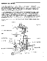
SYSTEM 100 LBS CONCORTM TM CR 40+ EXERCISES TRIADTM LEG SYSTEM Serial Number Decal - QUESTIONS? As a manufacturer, we are committed to providing you complete customer satisfaction. If you have questions, or find there are missing or damaged parts, we will guarantee you complete satisfaction - ProForm 300 Ci | English Manual - Page 2
and Fitness Inc. TABLE OF CONTENTS IMPORTANT SAFETY PRECAUTIONS BEFORE YOU BEGIN ASSEMBLY USING THE PROFORM© 300 CR TROUBLE-SHOOTING AND MAINTENANCE PART LIST/EXPLODED DRAWING ORDERING REPLACEMENT PARTS WARRANTY 2 3 4 19 21 22 Back Cover Back Cover IMPORTANT SAFETY PRECAUTIONS WARNING: To reduce - ProForm 300 Ci | English Manual - Page 3
PROFORM© 300 CR cross training system. The innovative PROFORM 300 CR offers an impressive array of weight training and aerobic exercises owner's manual and the accompanying literature before using the PROFORM 300 CR. If you have additional questions, please call our Customer Service Department toll - ProForm 300 Ci | English Manual - Page 4
, read each step and examine each drawing carefully. Make sure that all parts are oriented as shown in the drawings. Refer to the PART IDENTIFICATION (ID) CHART accompa- nying this owner's manual for help identifying the small parts used in assembly. Due to the size and weight of the cross training - ProForm 300 Ci | English Manual - Page 5
6 3/4" Round Inner Cap (30) into each side of the Arm Support. Grease • 86 , ! Apply grease to the rod of the Arm Support (85). Turn an Arm Support Bushing (92) so the P 28 I ?"30 , . rounded groove is on top. Place the Arm Support Bushing on top of the plate on the 85 ' Top Brace (86 - ProForm 300 Ci | English Manual - Page 6
8. Press two 1 3/4" x 1 3/4" Inner Caps (28) into each of the Arms (51). - 8 Apply grease to the axles on the Arm Support (85). Slide an Arm (51) onto the right axle. Hold two 1 5/16" Retainer Rings (38) and a 1" Plastic Cap (37) against the lower end of the - ProForm 300 Ci | English Manual - Page 7
10. Attach a 3 1/2"U" Bracket (98) to the left Arm (51) with a 5/16" x 2 1/2" Bolt (20), 3/8' Washer (8) and 5/16" Nylock Nut (4). Do not overtighten the Nylock Nut-the "U" Bracket must be able to pivot freely. Attach a Thin 'L' Bracket (99) to the 3 1/2" "U" Bracket (98) with a 5/16" x 2 1/4" Bolt - ProForm 300 Ci | English Manual - Page 8
14. Place a Foot Pad (62) on the end of the Right Pedal (64). Attach the Foot Pad with a 1/2" 14 Pan Screw (45). Attach the other Foot Pad (62) to the Left Pedal (63) in the same manner. 45 64 62 4,0 63 62 4{15. Apply grease to the cylinder axles on the Rear Upright (74). 15 Slide a - ProForm 300 Ci | English Manual - Page 9
18. Attach a VKR Armrest (58) to each VKR Arm (57) with two 1/4" x 2" Screws (9) and 1/4" 18 Washers (1). Attach the VKR Backrest (59) to the Rear Upright (74) with two 1/4" x 2 1/2" Screws (2) and 1/4" Washers (1). 59 58 58 , 57 . 11 57 ...,.d 2 74 19. Insert the end of the Handle (52) - ProForm 300 Ci | English Manual - Page 10
- 22. Attach the Backrest (78) to the Front Upright 0 22 (76) with two 1/4" x 2 1/2" Screws (2) and 1/4" Washers (1). ' ..-- I 'L.-- - -\. 1 , _ . 78 23. Insert a 3/8" x 2 3/4" Bolt (16) into one side of the Top Brace (86). Slide a 3/8" x 3/8" Metal Spacer (6) onto the Bolt. Lay the ball - ProForm 300 Ci | English Manual - Page 11
- 26. Route the end of the Short Cable (94) around the indicated 3 1/2" Pulley (55) in the "I° 26 Plates (75). Insert a 3/8" x 2 3/4" Bolt (16) into one side of the Top Brace (86). Slide a 3/8" x 3/8" Metal Spacer (6) onto the Bolt. Lay the Short Cable (94) over a 3 1/2" Pulley (55). Slide the - ProForm 300 Ci | English Manual - Page 12
93 15 32. Route the Long Cable (93) over the 3 1/2" Pulley (55) at the lower end of the "I" Plates 32 (75). Slide a Plastic Cable Guide (18) and a 3 1/2" Pulley (55) onto a 3/8" x 3 3/4" Bolt (21). Insert the Bolt into the tube on the Front Upright (76) and tighten a 3/8" Nylock Nut (15) onto - ProForm 300 Ci | English Manual - Page 13
(86) with a 5/161 x 3 1/4" Bolt (19) and 5/16" Nylock Nut (4). Make sure that the Thick "L' Bracket is turned as shown. Slide a Plastic Cable Guide (18) and a 3 1/2" Pulley (55) onto a 3/8" x 1 3/4" Bolt (26). Insert the Bolt into the Thick "L" Bracket (100) and tighten a 3/8" Nylock Nut (15) onto - ProForm 300 Ci | English Manual - Page 14
the sides of the Weight (79) on the Weight Selector (82). 40. Insert a 5/16" x 4 1/4" Bolt (41) through the upper end of one of the Weight Guides (83). 40 Slide a 2 5/8" Metal Spacer (42) onto the Bolt and insert the Bolt into the Top Brace (86). Tighten a 5/16" Nylock Nut (4) onto the Bolt - ProForm 300 Ci | English Manual - Page 15
Weight Selector into the Weights. ( - ) 42. Open a Weight Sleeve (80) and close it around one of the Weight Guides (83). Close 42 the other Weight Sleeve (80) around the other Weight Guide. Turn the Weight Sleeves so the hinged sides are toward each other. ._ • 82 , . Pin Grooves 83 80 - ProForm 300 Ci | English Manual - Page 16
Top Brace (86). Remove the "DUAL FUNCTION PRESS ARM" decal from the Decal Sheet (not shown). Center the decal on the front of the Arm Support (85). Remove the "ACTUAL RESISTANCE FOR BENCH PRESS . . ." decal from the Decal Sheet (not shown). Apply the decal to the left Arm (51). 47. Remove - ProForm 300 Ci | English Manual - Page 17
49. Remove the "TRIAD LEG SYSTEM" decal 49 from the Decal Sheet (not shown). Apply the decal to the corner of the Leg Press Plate (70). "TRIAD LEG SYSTEM" 70 50. Remove the ten small decals numbered "10" through "100" from the Decal Sheet (not shown). Apply the decals to the ten Weights (79) - ProForm 300 Ci | English Manual - Page 18
use of all remaining parts will be explained in USING THE PROFORM 300 CR, beginning on page 19 of this owner's manual. WARNING: For your If either of the cables does not move smoothly, locate and correct the problem before using the cross training system. IMPORTANT: If the cables are not properly - ProForm 300 Ci | English Manual - Page 19
USING THE PROFORM 300 CR The instructions below describe how each part of the cross training system can be adjusted. See the EXERCISE GUIDE accompanying this owners manual to see how the cross training system should be set up for each individual exercise. CHANGING THE WEIGHT SETTING The weight - ProForm 300 Ci | English Manual - Page 20
position. Insert the two 4 1/2" "L" Pins (43) down through the Arm Support and the Arms. IMPORTANT: Always lock the arms in the stationary position with the 4 1/2" "L" Pins except when performing the butterfly or reverse butterfly exercise. .__20 ATTACHING THE LAT BAR OR NYLON STRAP TO THE HIGH - ProForm 300 Ci | English Manual - Page 21
TROUBLE-SHOOTING AND MAINTENANCE Inspect and properly tighten all parts of the cross training system each time you exercise. Replace any worn parts enough by turning the Nylock Nut, see the instructions below. 76 1 E3 4 27 Locate the two manual to order new cables. 55 75 15 26 55 21 - ProForm 300 Ci | English Manual - Page 22
17 1 Decal Sheet 18 6 Cable Guide 19 1 5/16" x 3 1/4" Support Bushing Long Cable Short Cable 1 1/2" x 1 1/ 5 6" "L" Pin 3" "U" Bracket 3 1/2" "U" Bracket Thin "L" Bracket Thick "L" Bracket Owner's Manual Part Identification Chart Exercise Manual Note: "#" indicates a non-illustrated part - ProForm 300 Ci | English Manual - Page 23
14 15 4 Ntl l 55 24 11 4 e--18\ 91 Y1W- 24 19 42 87 89 88 11 ) 19) 52 4 1 92 11 99 4 55 4 95 42 3 11,b 10 98 14P 11 51 ) 1E-47. 99 'f2 4 9 30 pi ty, 23 55 1 26' • -4100 re', 52-„, 10 12 i 59 15 58 55 18 11 r --61- 4r V" 13 6 rcc 16> 16 95 57 84 53 c:2 20 ofr 8 - ProForm 300 Ci | English Manual - Page 24
of the product (PROFORM® 300 CR cross training system). 3. The SERIAL NUMBER of the product (see the front cover of this manual). 4. The KEY NUMBER and DESCRIPTION of the part(s) from the PART LIST/EXPLODED DRAWING accompanying this owner's manual. LIMITED WARRANTY Proform Fitness Products, Inc
-
 1
1 -
 2
2 -
 3
3 -
 4
4 -
 5
5 -
 6
6 -
 7
7 -
8
-
9
-
10
-
11
-
12
-
13
-
14
-
15
-
16
-
17
-
18
-
19
-
20
-
21
-
22
-
23
-
24
 |
 |

PRO-FORM
Serial
Model
Serial
No.
PF803030
No.
Number
Decal
-
QUESTIONS?
As
a
manufacturer,
we
are
committed
to
providing
you
complete
customer
satisfac-
tion.
If
you
have
questions,
or
find
there
are
missing
or
damaged
parts,
we
will
guarantee
you
complete
satisfaction
through
direct
assistance
from
our
factory.
TO
AVOID
UNNECESSARY
DELAYS,
PLEASE
CALL
DIRECT
TO
OUR
TOLL
-FREE
CUSTOMER
HOT
LINE.
The
trained
technicians
on
our
customer
hot
line
will
provide
immediate
assis-
tance,
free
of
charge
to
you.
CUSTOMER
HOT
LINE:
1-800-999-3756
Mon.
—Fri.,
6
a.m.-6
p.m.
MST
CAUTION!
Read
all
safety
precautions
and
instructions
in
this
manual
before
using
this
equipment.
Save
this
manual
for
future
reference.
PATENT
PENDING
TM
CR
CRO$8:rLIAINING
SYSTEM
40+
EXERCISES
100
LBS
CONCORTM
TRIADTM
LEG
SYSTEM
OWNER'S
MANUAL