ProForm 380 Cs Treadmill English Manual - Page 9
If You Do Not Connect The Con
 |
View all ProForm 380 Cs Treadmill manuals
Add to My Manuals
Save this manual to your list of manuals |
Page 9 highlights
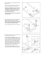
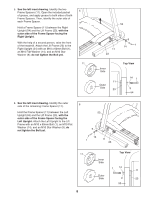
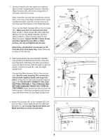
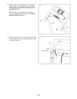
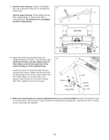
7. Set the Console (91) face down on a soft sur- 7 face to avoid scratching the Console. Hold the Right Handrail (33), which has a large hole in one side, near the Console. Console Wire 85 Tie Next, insert the console wire and the tie into the Bracket 7 10 hole in the side of the Right Handrail (33). Using needlenose pliers, pull the console wire out of the hole near the bracket on the Right Handrail. Then, set the Right Handrail (33) on the Console Large 33 Hole (91). Make sure that no wires are pinched. Start an M5 x 16mm Screw (85) with a M5 Star 91 Washer (7) into the Right Handrail, and then start two M4.2 x 19mm Screws (10) into the Right Handrail. Tighten the M5 x 16mm Screw and then tighten the two M4.2 x 19mm Screws; do not overtighten the Screws. Attach the Left Handrail (not shown) to the Console (91) in the same way. Note: There are no wires on the left side. 8. Remove the plastic ties from the Right Handrail (33) and the Left Handrail (not shown). Press the two Cage Nuts (105) back into place if necessary (only one side is shown). With the help of a second person, hold the Console (91) near the Right Upright (54). Connect the Wire Harness (39) to the console wire. See the inset drawing. The connectors should slide together easily and snap into place. If they do not, turn one connector and try again. IF YOU DO NOT CONNECT THE CONNECTORS PROPERLY, THE CONSOLE MAY BECOME DAMAGED WHEN YOU TURN ON THE POWER. Next, remove the wire tie from the Wire Harness. Insert the connectors and the excess wire downward into the Right Upright (54). 8 33 39 54 91 105 Console Wire Wire Tie 39 9. Attach the Console (91) to the Uprights (53, 54) with four M8 x 15mm Bolts (8) and four M8 Star 9 91 Washers (5); do not fully tighten the Bolts yet. Make sure that no wires are pinched. 8 5 54 9 8 5 53
-
 1
1 -
2
-
3
-
 4
4 -
 5
5 -
 6
6 -
 7
7 -
 8
8 -
 9
9 -
 10
10 -
 11
11 -
 12
12 -
 13
13 -
 14
14 -
15
-
16
-
17
-
18
-
19
-
20
-
21
-
22
-
23
-
24
-
25
-
26
-
27
-
28
 |
 |
