ProForm 570 Crosswalk Treadmill English Manual - Page 11
Sole May Be Damaged When
 |
View all ProForm 570 Crosswalk Treadmill manuals
Add to My Manuals
Save this manual to your list of manuals |
Page 11 highlights
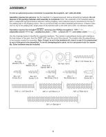
11. Set the console assembly face down on a soft surface to avoid scratching the console assem- 11 bly. Remove the two #8 x 3/4" Screws (1). Lift off the Pulse Bar (110). Save the Pulse Bar and the two Screws for assembly steps 12 and 14. 110 1 12. Set the Pulse Bar (110) on the Left and Right Uprights (77, 92). Attach the Pulse Bar with four #10 x 3/4" Screws (4) and four #10 Star Washers (12). Start all four Screws before firmly tightening any of them. Be careful not to pinch the Wire Harness (91). Firmly tighten the four 5/16" x 1 3/4" Bolts (5). 12 4 12 5 77 Console Assembly 110 4 12 5 91 92 13. While a second person holds the console assembly near the Pulse Bar (110), connect the Console Ground Wire (109) on the Pulse Bar to the ground wire from the console assembly. Connect the console wire to the Wire Harness (91). See the inset drawing. The connectors should slide together easily and snap into place. If they do not, turn one connector and then try again. IF THE CONNECTORS ARE NOT CONNECTED PROPERLY, THE CONSOLE MAY BE DAMAGED WHEN THE POWER IS TURNED ON. Lay the wires inside the bottom of the Pulse Bar (110). 13 Console Console Assembly Wire Ground Wire 109 110 91 Console Wire 91 11
-
 1
1 -
2
-
3
-
4
-
5
-
 6
6 -
 7
7 -
 8
8 -
 9
9 -
 10
10 -
 11
11 -
 12
12 -
 13
13 -
 14
14 -
 15
15 -
 16
16 -
17
-
18
-
19
-
20
-
21
-
22
-
23
-
24
-
25
-
26
-
27
-
28
-
29
-
30
-
31
-
32
 |
 |
