ProForm 580 Cs Treadmill English Manual - Page 11
Attach the Left Handrail Cover 78 in
 |
View all ProForm 580 Cs Treadmill manuals
Add to My Manuals
Save this manual to your list of manuals |
Page 11 highlights
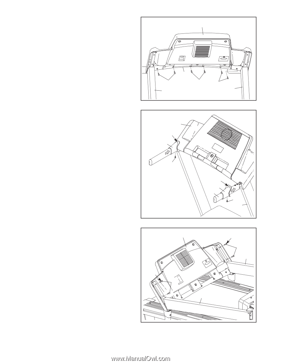
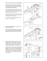
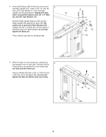
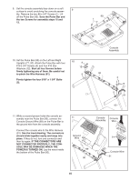
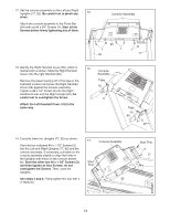
12. Set the console assembly on the Left and Right Uprights (77, 92). Be careful not to pinch any 12 wires. Attach the console assembly to the Pulse Bar (90) with six #8 x 3/4" Screws (1). Start all six Screws before firmly tightening any of them. Console Assembly 90 1 1 92 1 77 13. Identify the Right Handrail Cover (55), which is marked with a sticker. Slide the Right Handrail Cover onto the right Handrail (80). 13 Console Assembly Remove the paper backing off of the tape in the indicated location and press the Right Handrail Cover (55) against the console assembly. Tighten a #8 x 1/2" Screw (2) into the Right Handrail Cover and the Right Upright (92); be careful not to overtighten the Screw. Tape 78 2 Attach the Left Handrail Cover (78) in the same way. Tape 55 80 2 92 14. Carefully lower the Uprights (77, 92) as shown. Start the two indicated #8 x 1 1/2" Screws (3) into the Left and Right Uprights (77, 92) and the console assembly. If necessary, pull back on the console assembly slightly to align the holes in the Uprights with those on the console assembly. Start the other two #8 x 1 1/2" Screws (3) and then tighten all four Screws; do not overtighten the Screws. Then, raise the Uprights. See steps 4 and 6. Firmly tighten the four 3/8" x 4" Bolts (8). 14 Console Assembly Start First 3 92 Start First 3 77 11
-
 1
1 -
2
-
3
-
4
-
5
-
 6
6 -
 7
7 -
 8
8 -
 9
9 -
 10
10 -
 11
11 -
 12
12 -
 13
13 -
 14
14 -
 15
15 -
 16
16 -
17
-
18
-
19
-
20
-
21
-
22
-
23
-
24
-
25
-
26
-
27
-
28
-
29
-
30
-
31
-
32
 |
 |