ProForm 7.25q Uk Manual - Page 8
Warning:
 |
View all ProForm 7.25q manuals
Add to My Manuals
Save this manual to your list of manuals |
Page 8 highlights
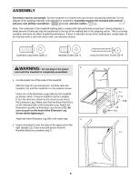
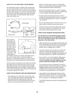
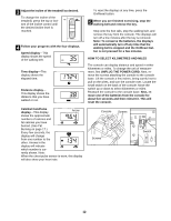
7. Place the Console Base (46) on the Handrails (1) (only the 7 Right Handrail is shown). Pull out just enough of the three Wires (21) to connect them to the receptacles in the 1 Console Base. Make a loop with the indicated plastic tie and insert the two Wires through the loop. Locate the Wire Tie that has a two-pin connector and a three-pin connector on the end. Plug the connectors into the matching recepta- cles in the Console Base. If the connectors do not fit easily, rotate them and then plug them in. Slide the Wire Cover (66) onto the connectors so that they are com- pletely covered. Next, plug the large Wire into the match- 21 ing receptacle on the Console Base. Then, plug the small wire into the wire on the Console Base. WARNING: Do not connect or disconnect the Wires whilst the tread- 66 mill power cord is plugged in. Tighten the plastic tie and cut off the end. See the inset drawing. Loop one of the included plastic ties around the Wire Cover (66) so that the plastic tie is in the two notches in the Wire Cover. Tighten the plastic tie and cut 8 off the end. 8. Thread four Long Screws (3) into the Handrails (1) and the Console Base (46). Make sure that the wires in the Right Handrail are clear of the screw holes. After all four Long Screws have been started, tighten them until they are snug; do not overtighten them. The console requires three 1.5 V batteries. Alkaline batteries are recommended. To install batteries, first touch the Uprights (11) to discharge any static. Next, open the Battery Cover (4) as shown. Insert three batteries into the battery compartment, making sure that the negative (-) ends of the batteries are touching the springs in the battery compartment. Close the Battery Cover, push up on the tab, and then push the tab forward as shown in the inset drawing. Make sure that the tab locks into place. Remove the plastic ties used in step 6. 4 Batteries 3 1 46 66 Tie 46 3 4 Tab 9. Make sure that all parts are properly tightened before you use the treadmill. Keep the included allen wrench in a secure place. The allen wrench is used to adjust the walking belt (see page 16). To protect the floor or carpet, place a mat under the treadmill. 8
-
 1
1 -
2
-
 3
3 -
 4
4 -
 5
5 -
 6
6 -
 7
7 -
 8
8 -
 9
9 -
 10
10 -
 11
11 -
 12
12 -
 13
13 -
14
-
15
-
16
-
17
-
18
-
19
-
20
-
21
-
22
-
23
 |
 |
