ProForm 765x Treadmill English Manual - Page 5
Assembly
 |
View all ProForm 765x Treadmill manuals
Add to My Manuals
Save this manual to your list of manuals |
Page 5 highlights
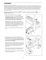
ASSEMBLY Assembly requires two persons. Set the treadmill in a cleared area and remove all packing materials. Do not dispose of the packing materials until assembly is completed. Note: The underside of the treadmill walking belt is coated with high-performance lubricant. During shipping, a small amount of lubricant may be transferred to the top of the walking belt or the shipping carton. This is a normal condition and does not affect treadmill performance. If there is lubricant on top of the walking belt, simply wipe off the lubricant with a soft cloth and a mild, non-abrasive cleaner. Assembly requires the included allen wrenches and your own phillips screwdriver and wire cutters . 1. Make sure that the power cord is unplugged. 1 To identify small parts, use the PART IDENTIFICATION CHART on page 27. Note: If a part is not in the parts bag, check to see if it has been pre-assembled. If a part is missing, call toll-free 1-888-533-1333. With the help of a second person, carefully raise the Upright Base (97) to the position shown. Insert one of the Extension Legs (92) into the Upright Base. (Note: It may be helpful to tip the Upright Base forward as you insert the Extension Leg.) Make sure that the Warning Decal (91) is in the indicated location. Insert the other Extension Leg (not shown) in the same way. 91 97 92 2. With the help of a second person, carefully tip the Upright Base (97) down as shown. (Note: It may be helpful to place your foot on one of the Extension Legs [92] as you tip the Uprights.) Make sure that the Extension Legs remain in the Uprights. Attach each Extension Leg (92) with two Extension Leg Bolts (96) and two 1/4" Washers (39) as shown. Thread a Leveling Foot (95) into each side of the Upright Base (97); do not thread the Leveling Feet fully into the Upright Base. Attach the two Base Pads (99) to the Upright Base (97) in the locations shown with two 1" Tek Screws (40). With the help of a second person, raise the Upright Base (97) to the vertical position. 2 99 40 39 97 92 39 96 97 95 92 39 96 99 40 96 95 96 5
-
 1
1 -
 2
2 -
 3
3 -
 4
4 -
 5
5 -
 6
6 -
 7
7 -
 8
8 -
 9
9 -
 10
10 -
 11
11 -
12
-
13
-
14
-
15
-
16
-
17
-
18
-
19
-
20
-
21
-
22
-
23
-
24
-
25
-
26
-
27
-
28
-
29
-
30
 |
 |
