ProForm 8.4s English Manual - Page 5
Electronic
 |
View all ProForm 8.4s manuals
Add to My Manuals
Save this manual to your list of manuals |
Page 5 highlights
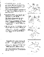
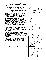
6. Slide the lower end of the Left Handlebar (4) onto the upper post on the Upright (6). Rotate the Right Handlebar (5) down and slide the lower end onto the upper post on the Upright. Set the Handlebar Plate (2) on the Upright. Insert the Sensor Wire (10) through the indicated slot in the Handlebar Plate. Do not let the Sensor Wire slip through the slot until assembly step 6 is completed. Push the lower ends of the Handlebars tight against the Upright and tighten the two M5 Screws (31). Replace the two M4 Screws (30) in the right side'of the Handlebar Plate (2). Tighten the Screws in both sides of the Handlebar Plate. Tighten the two M10 Plate Screws (25) through the Upright (6) into the Handlebar Plate. 7. The Electronic Monitor (1) requires two "AA" batteries (not included); alkaline batteries are recommended. Slide open the battery cover and remove the battery clip from the Monitor (see the inset drawing). Find the markings inside the battery clip showing which direction the batteries must be turned. Press two batteries into the battery clip. Replace the battery clip in the Monitor and close the battery cover. Connect the Sensor Wire (10) to the wire extending from the Electronic Monitor (1). Attach the Monitor to the Handlebar Plate (2) with the four Monitor Screws (3). Be careful not to damage the wires. 8. Slide a Cylinder Spacer (12) and a Resistance Cylinder (7) onto each of the lower posts on the Upright (6). Make sure that the Resistance Cylinders are turned so the arrows are on the side shown. Tap a Dome Cap (11) onto the end of each post. Attach the lower ends of the Resistance Cylinders (7) to the brackets on the flight and Left Pedals (18, 19) with the two M10 Bolts (26) and two M10 Nylock Nuts (24). 9. Attach the Water Bottle Bracket (35) to the Upright (6) with the two M4 Bracket Screws (34). Slide the Water Bottle (27) into the Bracket. 6 30 25 6 4 31 10 5 7 • Battery Clip 10 3 3 2 8 6 11 Arrow 7 12 12 19 18 11 7 24 26 9 27 6 35 5
-
 1
1 -
 2
2 -
 3
3 -
 4
4 -
 5
5 -
 6
6 -
 7
7 -
 8
8 -
 9
9 -
 10
10 -
 11
11 -
12
 |
 |
