ProForm 900 English Manual - Page 6
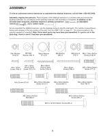
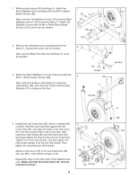
Stabilizer Covers with six M4 x 16mm Round Head
 |
View all ProForm 900 manuals
Add to My Manuals
Save this manual to your list of manuals |
Page 6 highlights
1. While another person lifts the Base (1), attach the Front Stabilizer (6) to the Base with two M10 x 82mm Button Screws (82). 1 82 6 Next, hold the Left Stabilizer Cover (118) and the Right Stabilizer Cover (119) around the Base (1). Attach the Stabilizer Covers with six M4 x 16mm Round Head 119 Screws (101) (only three are shown). 118 2. Remove the indicated screw and bracket from the Base (1). Discard the screw and the bracket. Next, turn the Base Foot (26) into the Base (1) as far as possible. 3. Attach the Rear Stabilizer (7) to the Frame (2) with two M10 x 127mm Button Screws (83). Next, hold the handle on the Frame (2), press the Latch Button (68), and lower the Frame until the Rear Stabilizer (7) is resting on the floor. 101 2 1 26 Screw 3 83 7 Handle 1 Bracket 4. Identify the Left Crank Arm (36), which is marked with a sticker. Hold the Left Crank Arm against the left Crank Hub (38), and align the holes in the Left Crank Arm with the unused holes in the Crank Hub. Next, insert four Hub Screws (87) into the Left Crank Arm, and finger tighten the Hub Screws into the Crank Hub. Tighten one of the Hub Screws, and then tighten the Hub Screw farthest from the first Hub Screw. Then, tighten the remaining two Hub Screws. Attach a Hub Cover (75) to the Left Crank Arm (36) with four M8 x 15mm Button Screws (116). Repeat this step on the other side of the elliptical exerciser. Make sure that the Crank Arms (36, 123) are oriented as shown. 6 4 38 75 87 116 87 116 Cutout 2 68 123 36
-
 1
1 -
 2
2 -
 3
3 -
 4
4 -
 5
5 -
 6
6 -
 7
7 -
 8
8 -
 9
9 -
 10
10 -
 11
11 -
 12
12 -
13
-
14
-
15
-
16
-
17
-
18
-
19
-
20
-
21
-
22
-
23
-
24
 |
 |
