ProForm 965 R User Manual - Page 6
Tighten all four Hex, Head Screws.
 |
View all ProForm 965 R manuals
Add to My Manuals
Save this manual to your list of manuals |
Page 6 highlights
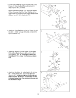
5. Connect the Reed Switch Wire (13) to the wire on the Console (8). Next, attach the Console (8) to the Upright (2) with four #8 x 5/8Ó Screws (22). Press the Resistance Knob (9) onto the Resistance Control (10). Be sure that the mark on the Knob is correctly aligned. 5 8 Console Wire 2 13 22 9 10 22 6. Finish attaching the Handlebar (4) to the Upright (2) 6 with two additional M6 x 25mm Hex Screws (14) and M6 Split Washers (67). Tighten all four Hex Head Screws. 67 14 7. Attach the Seat Bracket (69) to the Seat Frame (3) 7 with four M6 x 48mm Button Bolts (70) and four M6 Flat Washers (34). 14 67 4 2 70 70 34 34 69 8. Attach the Seat (16) to the Seat Bracket (69) with 8 four M6 x 16mm Phillips Screws (24). 6 3 16 69 24 24
-
 1
1 -
 2
2 -
 3
3 -
 4
4 -
 5
5 -
 6
6 -
 7
7 -
 8
8 -
 9
9 -
 10
10 -
 11
11 -
 12
12 -
13
-
14
-
15
-
16
 |
 |

6
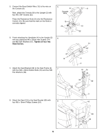
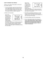
6.
Finish attaching the Handlebar (4) to the Upright (2)
with two additional M6 x 25mm Hex Screws (14)
and M6 Split Washers (67).
Tighten all four Hex
Head Screws.
7.
Attach the Seat Bracket (69) to the Seat Frame (3)
with four M6 x 48mm Button Bolts (70) and four M6
Flat Washers (34).
8.
Attach the Seat (16) to the Seat Bracket (69) with
four M6 x 16mm Phillips Screws (24).
69
69
3
70
34
34
70
24
24
16
14
14
2
4
6
7
67
67
5.
Connect the Reed Switch Wire (13) to the wire on
the Console (8).
Next, attach the Console (8) to the Upright (2) with
four #8 x 5/8± Screws (22).
Press the Resistance Knob (9) onto the Resistance
Control (10). Be sure that the mark on the Knob is
correctly aligned.
Console
Wire
10
8
9
13
2
22
22
5
8