ProForm 990 X Treadmill English Manual - Page 7
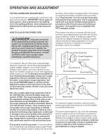
Damaged When The Power Is Turned On.
 |
View all ProForm 990 X Treadmill manuals
Add to My Manuals
Save this manual to your list of manuals |
Page 7 highlights
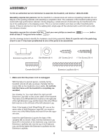
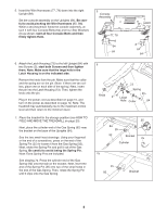
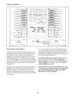
2. Attach two Base Pads (82) to the base of the Uprights (84) with two 1" Tek Screws (22) as shown. 2 84 82 82 22 3. Identify the Right Base Cover (107). Attach the Right Base Cover to the base of the Uprights (84) and the 3 Extension Leg (89) with five Screws (3). Be careful not to overtighten the Screws. 84 With the help of a second person, carefully tip the 107 treadmill onto its other side. Attach the left Extension Leg (not shown) as described in steps 1 through 3. 3 89 3 4. With the help of a second person, carefully raise the 4 Uprights (84) to a vertical position. Have the second person hold the console assembly near the right Upright (84) as shown. Look under the console assembly and locate the Console Wire Harness (78). Cut the plastic ties securing the Upright Wire Harness (77) to the right Upright (84). Next, connect the Upright Wire Harness to the Console Wire Harness (78). Make sure to connect the connectors properly (see the inset drawing). The connectors should slide together easily and snap into place. If they do not, turn one connector and try again. IF THE CONNECTORS ARE NOT CONNECTED PROPERLY, THE CONSOLE MAY BE DAMAGED WHEN THE POWER IS TURNED ON. Console Assembly 78 77 78 77 84 7
-
 1
1 -
 2
2 -
 3
3 -
 4
4 -
 5
5 -
 6
6 -
 7
7 -
 8
8 -
 9
9 -
 10
10 -
 11
11 -
 12
12 -
13
-
14
-
15
-
16
-
17
-
18
-
19
-
20
-
21
-
22
-
23
-
24
-
25
-
26
-
27
-
28
-
29
-
30
-
31
-
32
 |
 |
