ProForm Crosswalk 325 Treadmill Canadian English Manual - Page 5
Assembly - parts
 |
View all ProForm Crosswalk 325 Treadmill manuals
Add to My Manuals
Save this manual to your list of manuals |
Page 5 highlights
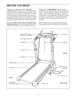
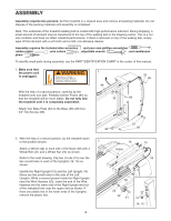
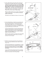
ASSEMBLY Assembly requires two persons. Set the treadmill in a cleared area and remove all packing materials. Do not dispose of the packing materials until assembly is completed. Note: The underside of the treadmill walking belt is coated with high-performance lubricant. During shipping, a small amount of lubricant may be transferred to the top of the walking belt or the shipping carton. This is a normal condition and does not affect treadmill performance. If there is lubricant on top of the walking belt, simply wipe off the lubricant with a soft cloth and a mild, non-abrasive cleaner. Assembly requires the included allen wrenches and your own phillips screwdriver , rubber mallet , wire cutters , adjustable wrench , and needlenose pliers . To identify small parts during assembly, use the PART IDENTIFICATION CHART in the center of this manual. 1. Make sure that the power cord ! is unplugged. With the help of a second person, carefully tip the treadmill onto one side. Partially fold the Frame (84) so that the treadmill will be more stable. Do not fully fold the treadmill until it is completely assembled. Attach four Base Pads (33) to the Base (38) with four 3/4" Tek Screws (89). 1 84 33 33 89 89 33 38 89 2. With the help of a second person, tip the treadmill down to the position shown. 2 Attach a Wheel (42) to each side of the Base (38) with a Wheel Bolt (41) and a Wheel Nut (22) as shown. Refer to the inset drawing. Clip two U-nuts (10) over the two round holes in each of the Uprights (14, 15) as shown. Identify the Right Upright (15) and the Left Upright (14) (there are two small holes in the side of the Left Upright). While a second person holds the Right Upright near the Wire Harness (53), insert the end of the Wire Harness into the lower end of the Right Upright and out of the indicated hole near the upper end as shown. If there are plastic ties in the lower ends of the Uprights, remove the plastic ties. 5 14 Holes 15 53 38 22 42 41 10 14, 15
-
 1
1 -
 2
2 -
 3
3 -
 4
4 -
 5
5 -
 6
6 -
 7
7 -
 8
8 -
 9
9 -
 10
10 -
 11
11 -
12
-
13
-
14
-
15
-
16
-
17
-
18
-
19
-
20
-
21
-
22
-
23
 |
 |
