ProForm E35s English Manual - Page 8
the Screws into the Right Top Handgrip.
 |
View all ProForm E35s manuals
Add to My Manuals
Save this manual to your list of manuals |
Page 8 highlights
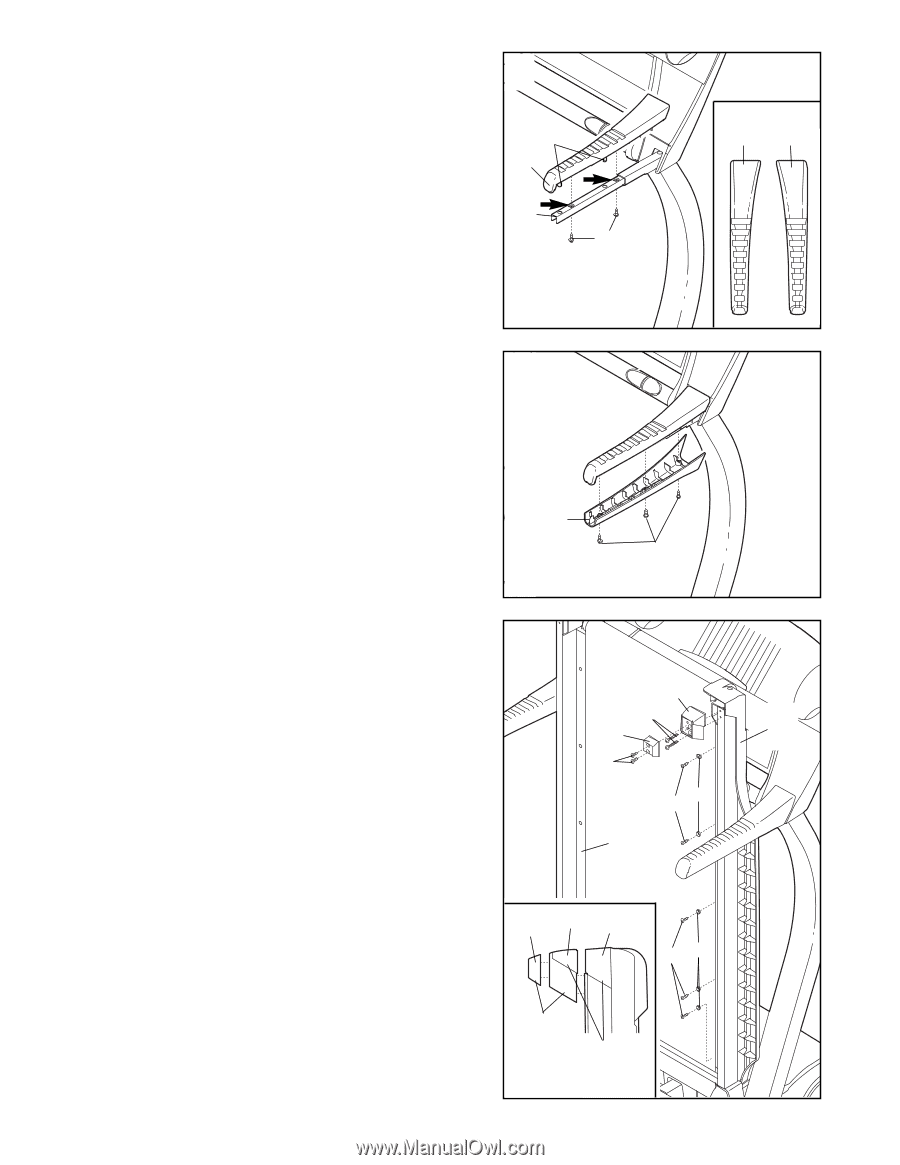
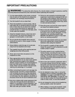
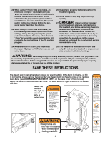
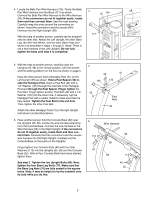
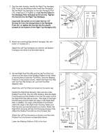
7. See the inset drawing. Identify the Right Top Handgrip (53); there are identifying marks inside the Handgrips. Set the Right Top Handgrip on the right Handgrip Post (41). Insert two 1/2" Screws (51) into the two holes in the Handgrip Post indicated by the arrows. Tighten the Screws into the Right Top Handgrip. Important: Be careful not to insert the two 1/2" Screws (51) into the wrong holes in the Handgrip Post (41), or tighten the Screws into the plastic bosses on the bottom of the Right Top Handgrip (53). 7 Bosses 53 41 51 Left Right 21 53 8. Attach the matching Right Bottom Handgrip (54) with three 1/2" Screws (51). 8 Attach the Left Top Handgrip (21) and the Left Bottom Handgrip (not shown) as described above. 54 51 9. Set the Right Foot Rail (98) and the Left Foot Rail (not shown) on the sides of the Walking Platform (100). While 9 a second person holds the Foot Rails, raise the Walking Platform to the position shown. Attach the Right Foot Rail with five Foot Rail Screws (97) and five Foot Rail Washers (96). 106 105 104 98 Attach the Left Foot Rail (not shown) in the same way. 45 Identify the Right Foot Housing (106) and one of the Rubber Feet (104). See the inset drawing. Hold the Right Foot Housing and the Rubber Foot near the upper end of the Right Foot Rail (98) as shown. The ridge on the Right Foot Housing should match the ridge on the Right Foot Rail. In addition, the angle of the Rubber Foot should match the angle of the Right Foot Housing. Make sure that the parts are oriented exactly as shown. Attach the Right Foot Housing with two Foot Housing Screws (105). Attach the Rubber Foot with two Foot Screws (45). 97 96 100 104 106 98 97 96 Attach the Left Foot Housing (not shown) and the other Rubber Foot (not shown) as described above. Lower the Walking Platform (100) to the floor. Matching Angles Ridges Side View 8
-
 1
1 -
2
-
 3
3 -
 4
4 -
 5
5 -
 6
6 -
 7
7 -
 8
8 -
 9
9 -
 10
10 -
 11
11 -
 12
12 -
 13
13 -
14
-
15
-
16
-
17
-
18
-
19
-
20
-
21
-
22
-
23
-
24
-
25
-
26
-
27
-
28
-
29
-
30
-
31
 |
 |