ProForm Edge 3001 English Manual - Page 6
Assembly
 |
View all ProForm Edge 3001 manuals
Add to My Manuals
Save this manual to your list of manuals |
Page 6 highlights
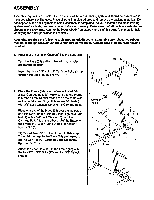
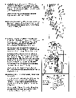
ASSEMBLY Assembly requires two people. Due to the size of the cross training system, it should be assembled in the place where it will be used. Place all parts in a cleared area and remove the packing materials. Do not dispose of the packing materials until assembly is completed. As you assemble the cross training system, read each step and examine each drawing carefully. Make sure that all parts are oriented as shown In the drawings. Refer to the PART CHART on pages 4 and 5 of this owners manual for help identifying the small parts used in assembly. Assembly requires the following tools (not Included): two 8" adjustable wrenches, two rubber mallets, a phillips screwdriver and a standard screwdriver. A small bowl of soapy water Is also required. 1. Press four 2' x 2' Inner Caps (25) into the Base (55). 1 Turn the Base (55) so the indented square holes are toward the floor. Insert the three 3/8' x 2 1/2' Carriage Bolts (3) up through the Base (55) as shown. 25 3 *V-25 2. Place the Frame (40) over the two indicated 3/8' x 2 1/2' Carriage Bolts (3). Make sure that the Frame 2 1\\ is turned so the cylinder axles are on the same side as the pedal axles. Finger tighten two 3/8' Nuts (1) with 3/8' Lock Washers (2) onto the Carriage Bolts. Cylinder A ...I..... rtA1GOO Place one end of the Brace (56) over the indicated 3/8' x 2 1/2' Carriage Bolt (3). Finger tighten a 3/8" Nut (1) with a 3/8' Lock Washer (2) onto the Carriage Bolt. Attach the other end of the Brace to the Frame (40) with a 3/8' x 3' Bolt (4) and 3/8' Nylock Nut (5). Tighten all four 3/8' Nuts (1) used in this step. To avoid damage to the Base (55), pull upward on the 3/8" x 21/2" Carriage Bolts (3) as you tighten the Nuts. 56 >. 4-e' 3 40 3 Pedal Axles 3. Attach the Foot Plate (35) to the Frame (40) with the two 3/8' x 3/4" Bolts (27) and two 3/8' Nylock 3 Nuts (5). 5 5 40 35 27
-
 1
1 -
 2
2 -
 3
3 -
 4
4 -
 5
5 -
 6
6 -
 7
7 -
 8
8 -
 9
9 -
 10
10 -
 11
11 -
 12
12 -
13
-
14
-
15
-
16
 |
 |
