ProForm Fusion 6.5 Lx English Manual - Page 7
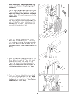
Note: If the Press Arm Cable not shown has
 |
View all ProForm Fusion 6.5 Lx manuals
Add to My Manuals
Save this manual to your list of manuals |
Page 7 highlights
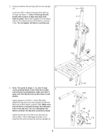
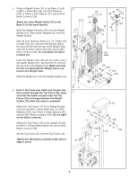
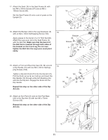
5. Attach a Weight Guide (13) to the Base (1) with 5 an M10 x 50mm Bolt (96), two M10 Washers (105), a 16mm x 6mm Spacer (11), and an M10 Nylon Locknut (108). Attach the other Weight Guide (13) to the Base (1) in the same manner. Slide two Weight Bumpers (29) onto the Weight Guides (13). Slide eleven Weights (27) onto the Weight Guides. See the inset drawing. Attach a 3 1/2" Pulley (43), a Cable Trap (47), and two Half Guards (48) to the second hole from the top of the Weight Tube (16) with an M10 x 50mm Bolt (96) and an M10 Nylon Locknut (108). Do not tighten the Nylon Locknut yet. Insert the Weight Tube (16) into the center hole in the twelfth Weight (27). Tap the Roll Pin (79) into the top hole in the Weight Tube. Make sure that the Pin is underneath the Weight and is centered in the Weight Tube. Slide the Weight (27) onto the Weight Guides (13). 6. Note: If the Press Arm Cable (not shown) has been routed through the Top Cover (24), make sure that the Cable crosses under the Top Frame (12) and hangs between the Weight Guides (13) while this step is completed. Attach the Top Frame (12) to the Weight Guides (13) with two M10 x 65mm Bolts (95), four M10 Washers (105), two 16mm x 12mm Spacers (81), and two M10 Nylon Locknuts (108). Do not tighten the Nylon Locknuts. Attach the Top Frame (12) to the Upright (3) with two M10 x 100mm Button Bolts (91) and an M10 Nylon Locknut (108). Set the Top Cover (24) over the Top Frame (12). Tighten the M10 Nylon Locknuts (108) used in steps 3 and 6. 6 91 48 43 13 48 13 47 16 108 79 96 16 27 27 Pin Hole 96 105 11 105 108 29 1 24 95 105 12 81 105 108 108 13 13 3 7
-
 1
1 -
 2
2 -
 3
3 -
 4
4 -
 5
5 -
 6
6 -
 7
7 -
 8
8 -
 9
9 -
 10
10 -
 11
11 -
 12
12 -
13
-
14
-
15
-
16
-
17
-
18
-
19
-
20
-
21
-
22
-
23
-
24
 |
 |
