ProForm Gl50 English Manual - Page 5
Shields 4, 5. Snap the Collar into the Side Shields.
 |
View all ProForm Gl50 manuals
Add to My Manuals
Save this manual to your list of manuals |
Page 5 highlights
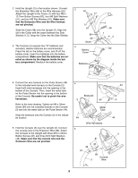
2. Hold the Upright (2) in the location shown. Connect the Extension Wire (66) to the Wire Harness (22). Attach the Upright to the Frame (1) with four M6 x 12.7mm Button Screws (62), four M6 Split Washers (57), and four M6 Flat Washers (67). Make sure that the Extension Wire and the Wire Harness are not pinched. Slide the Collar (48) onto the Upright (2). Align the slit in the Collar with the seam between the Side Shields (4, 5). Snap the Collar into the Side Shields. 3. The Console (3) requires four "D" batteries (not included); alkaline batteries are recommended. Press the tab on the battery cover, and lift off the battery cover. Insert four batteries into the battery compartment. Make sure that the batteries are oriented as shown by the diagram inside the battery compartment. Reattach the battery cover. 2 62 57 67 57 67 66 22 Seam 3 Battery Cover 2 48 1 45 Tab Batteries 3 4. Connect the wire harness on the Pulse Sensor (44) to the indicated wire harness on the Console (3). Insert both wire harnesses into the opening in the bottom of the Console. Then, insert the metal tube on the Pulse Sensor into the opening in the bottom of the Console. Be careful not to pinch the wire harnesses. Refer to the inset drawing. Tighten an M4 x 16mm Screw (64) into the indicated bracket on the Console (3) and into the metal tube on the Pulse Sensor (44). Snap the bookrack onto the Console (3) in the indicated location. 5. Hold the Console (3) near the Upright (2). Connect the console wire to the Extension Wire (66). Attach the Console to the Upright with three M10 x 25mm Button Screws (81) and three M10 Split Washers (46). Make sure that the console wire and the Extension Wire are not pinched. 4 44 Bookrack 3 64 3 Metal Tube 64 Wire Harnesses 5 81 46 46 81 66 Console 2 Wire 44 3 5
-
 1
1 -
 2
2 -
 3
3 -
 4
4 -
 5
5 -
 6
6 -
 7
7 -
 8
8 -
 9
9 -
 10
10 -
 11
11 -
12
-
13
-
14
-
15
-
16
-
17
-
18
-
19
-
20
 |
 |
