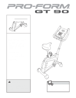
ProForm Gt 90 Bike English Manual - Page 6
M8 x 25mm Button Screws 19 and three M8 Split
 |
View all ProForm Gt 90 Bike manuals
Add to My Manuals
Save this manual to your list of manuals |
Page 6 highlights
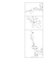
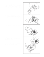
4. While another person holds the Handlebar (7) near 4 the Handlebar Post (6), feed the Upper Wire Harness (16) and the Pulse Sensor Wire (45) up through the indicated hole in the Handlebar. Attach the Handlebar to the Handlebar Post with three M8 x 25mm Button Screws (19) and three M8 Split Washers (28). Hole 45 7 6 28 19 16 28 19 5. The Console (9) requires four "D" batteries (not 5 included); alkaline batteries are recommended. Press the tab on the battery cover and remove the 9 battery cover. Press four batteries into the battery clips; make sure that the batteries are oriented Battery Cover as shown by the diagram inside the battery clips. Then, reattach the battery cover. 6. Insert the Bookrack (8) into the slots in the Console 6 (9). Attach the Bookrack with two M4 x 25mm Screws (20). Be careful not to pinch the wires in the Console. Batteries 8 9 7. While another person holds the Console (9) near 7 the Handlebar (7), connect the Pulse Sensor Wire (45) and the Upper Wire Harness (16) to the corre- sponding wires on the Console. Insert all excess wiring downward into the Handlebar Post (6). Attach the Console (9) to the Handlebar (7) with four M4 x 16mm Screws (21). Be careful not to pinch the Pulse Sensor Wires (45) or the Upper Wire Harness (16). 20 7 21 45 9 Console Wires 16 21 6 6
-
 1
1 -
 2
2 -
 3
3 -
 4
4 -
 5
5 -
 6
6 -
 7
7 -
 8
8 -
 9
9 -
 10
10 -
 11
11 -
 12
12 -
13
-
14
-
15
-
16
-
17
-
18
-
19
-
20
-
21
-
22
-
23
-
24
 |
 |
