Pyle PLCMDVR72 Instruction Manual
Pyle PLCMDVR72 Manual
 |
View all Pyle PLCMDVR72 manuals
Add to My Manuals
Save this manual to your list of manuals |
Pyle PLCMDVR72 manual content summary:
- Pyle PLCMDVR72 | Instruction Manual - Page 1
PLCMDVR72 MANUAL - Pyle PLCMDVR72 | Instruction Manual - Page 2
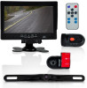
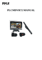
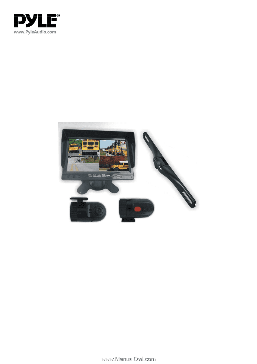
instructions If the unit malfunctions please return to yourvendor or send to a Pyle repair facility. Please observe and obey the local laws and regulations wiring diagram for connections between cameras, monitor and your vehicle. PLCMDVR72 INTRODUCTION This model is with one 7 inch quad monitor with - Pyle PLCMDVR72 | Instruction Manual - Page 3
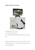
Monitor Wiring & Connection Red and black wire is for 12V power Green wire is Reverse trigger cable The 2 yellow RCA jack and red and white RCA jack is the 4 ch video input. The Reverse trigger cable is for the Ch1, so please connect the reverse backup camera to the Ch1, so when the truck in reverse - Pyle PLCMDVR72 | Instruction Manual - Page 4
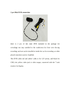
2 pcs Mini DVR connection there is 2 pcs of this mini DVR included in the package for recording( one may installed at the windscreen for front view driving recording, and one can be installed at inside the car for recording ,or other placed customers want to installed) The DVR cable red and yellow - Pyle PLCMDVR72 | Instruction Manual - Page 5
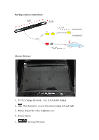
Backup camera connection: Monitor Buttons: 1. V1/V2: change the mode, 1 ch, 2ch,3ch,4ch display 2. This button for reverse the picture image left and right 3. Menu: Adjust the color, brightness, etc. 4. Power button 5. Increase/Decrease - Pyle PLCMDVR72 | Instruction Manual - Page 6
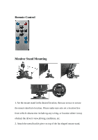
Remote Control Monitor Stand Mounting 1. Set the mount stand in the desired location, then use screws to secure the mount stand into location. Please make sure asto set a location free from vehicle obstruction include ng any wiring, or location where it may obstruct the driver's view,driving - Pyle PLCMDVR72 | Instruction Manual - Page 7
and slide it into the receiving slot in back of thedisplay monitor assembly. This metal buckle should slide in and up to the monitor assembly. 3. Set the desired position/height of the buckle into the monitor assembly. 4. Tighten the clamp‐style knob in the back of the stand mount to secure the
-
 1
1 -
 2
2 -
 3
3 -
 4
4 -
 5
5 -
 6
6 -
 7
7
 |
 |
PLCMDVR72 MANUAL