Pyle PLRD175IF PLRD175IF Manual 1 - Page 6
fCrt - 17 ' flip down monitor
 |
View all Pyle PLRD175IF manuals
Add to My Manuals
Save this manual to your list of manuals |
Page 6 highlights
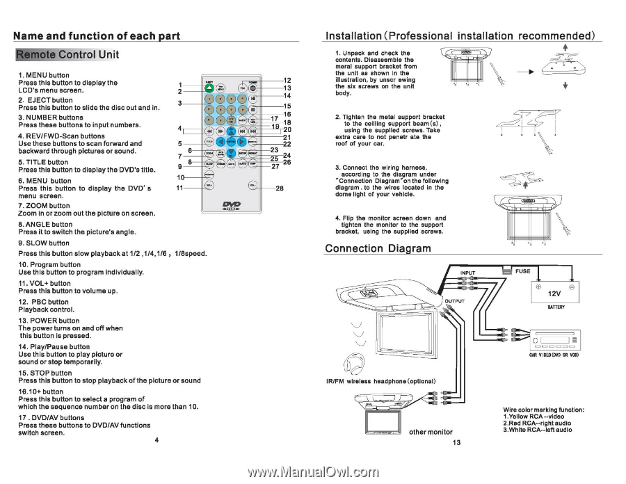
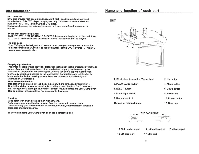
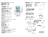
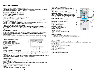
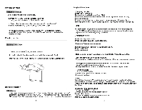
Name and function of each part U n i t 0 1. MENU button Press this button to display the LC~'s menu screen. 2. EJECT button Press this button to slide the disc out and in. 3. NUMBER buttons Press these buttons to input numbers. J===4fCrt-§·J 3---tl-,,= 4. REV/FWD-Scan buttons Use these buttons to scan forward and backward through pictures or sound. 5. TITLE button Press this button to display the DVD's title. 6. MENU button Press this button to display the DVD' s menu screen. 7. ZOOM button Zoom in or zoom out the picture on screen. ll---tl-~ S. ANGLE button Press it to switch the picture's angle. 9. SLOW button Press this button slow playback at 1/2 ,1/4,116, I/Sspeed. 10. Program button Use this button to program individually. 11. VOL+ button Press this button to volume up. 12. PBC button Playback control. 13. POWER button The power turns on and off when this button is pressed. 14. Play/Pause button Use this button to play picture or sound or stop temporarily. 15. STOP button Press this button to stop playback olthe picture or sound 16.10+ button Press this button to select a program of which the sequence number on the disc is more than 10. 17 . DVD/AV buttons Press these buttons to DVD/AV functions switch screen. 4 12 13 14 15 16 17 IS 0 1 22 23 25 24 27 26 2S Installation (Professional installation recommended) 1. Unpack and check the contents. Disassemble the meral support bracket from the unit as shown in the illustration. by unser ewing the six screws on the unit body. 2. Tighten the metal support bracket to the ceilling support beam (5) , using the supplied screws. Take extra care to not penetr ate the roof of your car. 3. Connect the wiring harness. according to the diagram under '" Connection Diagram'" on the following diagram. to the wires located in the dome light of your vehicle. 4. Flip the monitor screen down and tighten the monitor to the support bracket, using the supplied screws. Connection Diagram \ " ~I ~I v v v IR/FM wireless headphone(optional) other monitor 13 CAR VIDED (DYD OR VCO) Wire color marking function: 1.Yellow RCA --video 2.Red RCA--right audio 3.White RCA--Iefl audio
-
 1
1 -
 2
2 -
 3
3 -
 4
4 -
 5
5 -
 6
6 -
 7
7 -
 8
8 -
 9
9 -
 10
10
 |
 |