RCA L26HD31 User Guide & Warranty - Page 14
Connecting a Component with Composite Video Good, Composite Video Connection, Connecting a Component - tv codes
 |
UPC - 846042700733
View all RCA L26HD31 manuals
Add to My Manuals
Save this manual to your list of manuals |
Page 14 highlights
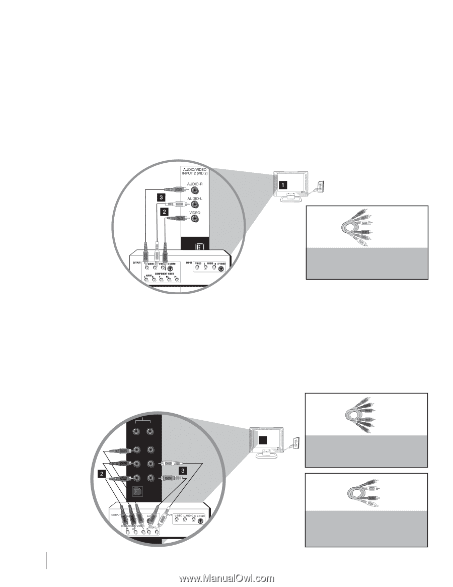
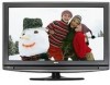
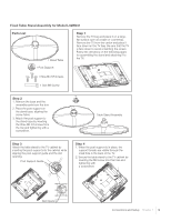
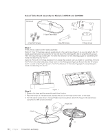
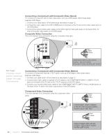
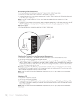
Connecting a Component with Composite Video (Good) To connect a component with a video output jack, such as a DVD player, follow these steps: Example: DVD Player 1. Connect your cable and/or off-air antenna as described on page 12. 2. Connect the video cable to the (VID1) VIDEO jack on the back of the TV and to the video output jack on the DVD player. 3. Connect the red and white audio cables to the (VID1) right and left audio jacks on the back of the TV and to the audio output jacks on the DVD player. Composite Video Connection This is an example of a connection using the composite video jack. Red White Yellow COMPOSITE CABLES ARE COLOR CODED-YELLOW=VIDEO; RED=RIGHT AUDIO; WHITE=LEFT AUDIO Don't forget: If necessary, connect antenna or cable to get a picture. Go to page 12 for instructions. Connecting a Component with Component Video (Better) To connect a component that has Y Pb Pr jacks, such as a DVD player, follow these steps: Example: DVD Player 1. Connect your cable and/or off-air antenna as described on page 12. 2. Connect three video cables or special Y Pb Pr cables to the COMPONENT INPUT 1 (CMPT) Y Pb Pr jacks on the back of the TV and to the Y Pb Pr outputs on the DVD player. 3. Connect your red and white audio cables to the COMPONENT INPUT (CMPT) R and L AUDIO jacks on the back of the TV and to the audio output jacks on the DVD player. Component Video Connection This is an example of a connection using the component video jacks. AUDIO R L 1 Y Video Pb L Pr R Optical Green Red Blue COMPONENT VIDEO CABLES (Y PB PR) ARE COLOR CODED- GREEN, BLUE AND RED Red White Antenna/Cable 14 Chapter 1 Connections and Setup AUDIO CABLES ARE COLOR CODED-RED=RIGHT AUDIO, WHITE=LEFT AUDIO
-
 1
1 -
2
-
3
-
4
-
5
-
6
-
7
-
8
-
 9
9 -
 10
10 -
 11
11 -
 12
12 -
 13
13 -
 14
14 -
 15
15 -
 16
16 -
 17
17 -
 18
18 -
 19
19 -
20
-
21
-
22
-
23
-
24
-
25
-
26
-
27
-
28
-
29
-
30
-
31
-
32
-
33
-
34
-
35
-
36
-
37
-
38
-
39
-
40
-
41
-
42
-
43
-
44
-
45
-
46
-
47
-
48
-
49
-
50
-
51
-
52
 |
 |