Reebok 1000 X Elliptical English Manual - Page 9
Tip: Remove the Ramp Cover
 |
View all Reebok 1000 X Elliptical manuals
Add to My Manuals
Save this manual to your list of manuals |
Page 9 highlights
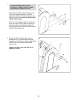
7. Identify and orient the Rear Stabilizer (2) as shown. Tip: Remove the Ramp Cover (not 7 shown) and set it aside until step 11. Lift the Ramp (55) and insert the Rear Stabilizer (2) into the Frame (1). Make sure to place the Ramp on the indicated Rollers (27). While a second person tips the Frame (1) forward, attach the Rear Stabilizer (2) with four M10 x 58mm Bolts (84) and four M10 Hex Nylon Locknuts (103). Tip: To prevent squeaking, do not overtighten the Bolts. 27 84 55 103 1 103 84 2 8. Cut and remove the wire tie that holds the Link 8 Tube (30) inside the left Link Arm (25). Leave the Link Tube inside the left Link Arm and then position the Left Pedal Leg (24) and the left Link Arm as shown. Apply a small amount of the included grease to a Barrel Nut (76). Insert the Barrel Nut through the indicated holes in the Left Pedal Leg (24) and the left Link Arm (25). Then, insert the Barrel Nut through the Link Tube (30) inside the left Link Arm. Tighten an M6 x 14mm Flat Head Screw (75) into the Barrel Nut (76). 25 Grease 30 76 24 Holes 75 9
-
 1
1 -
2
-
3
-
 4
4 -
 5
5 -
 6
6 -
 7
7 -
 8
8 -
 9
9 -
 10
10 -
 11
11 -
 12
12 -
 13
13 -
 14
14 -
15
-
16
-
17
-
18
-
19
-
20
-
21
-
22
-
23
-
24
-
25
-
26
-
27
-
28
-
29
-
30
-
31
-
32
 |
 |
