Reebok Cyc6 Bike English Manual - Page 5
two M8 Curved Washers 28, and two M8 Nylon
 |
View all Reebok Cyc6 Bike manuals
Add to My Manuals
Save this manual to your list of manuals |
Page 5 highlights
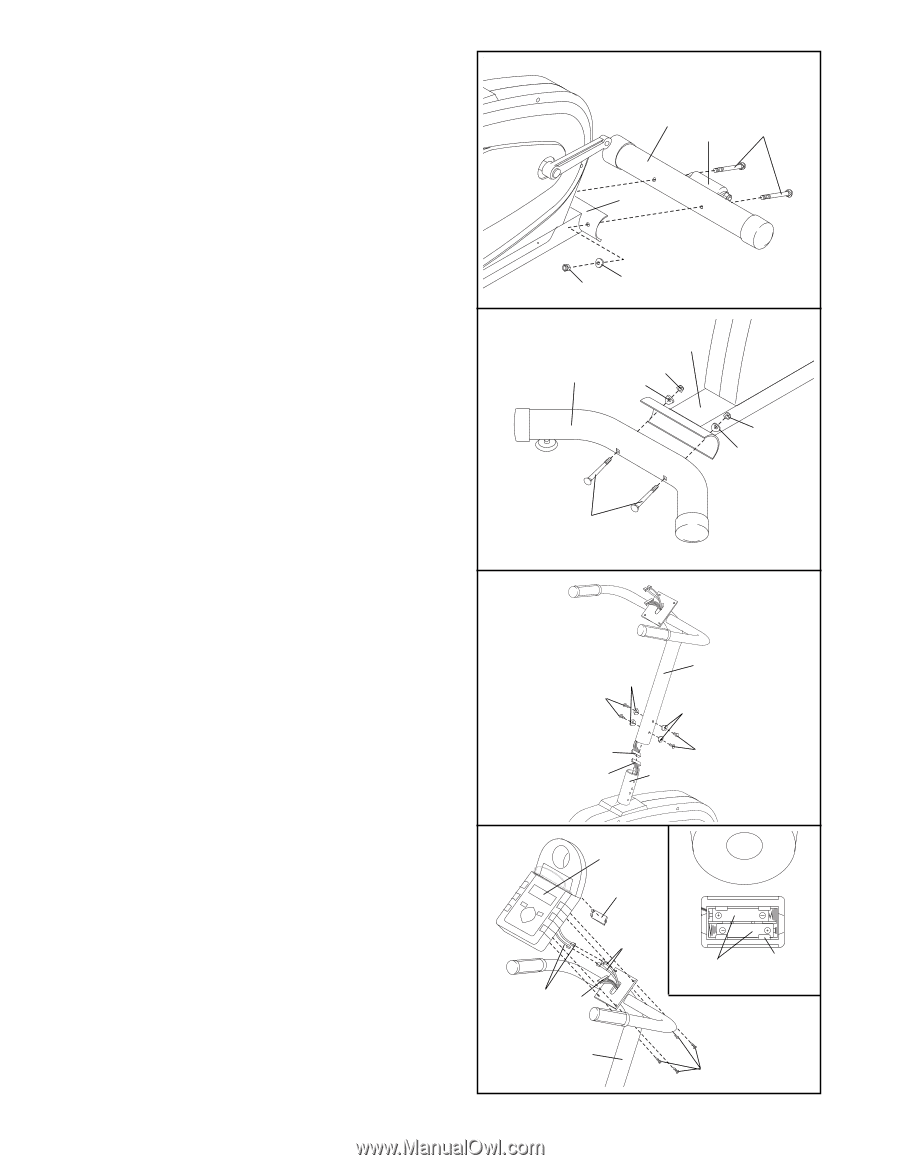
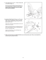
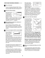
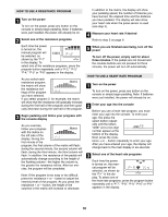
1. Attach the Front Stabilizer (2) to the front of the 1 Frame (1) with two M8 x 70mm Carriage Bolts (72), two M8 Curved Washers (28), and two M8 Nylon Locknuts (56). Make sure that the Front Stabilizer is turned so the Roller (75) is not touching the floor. 2 75 72 1 2. Attach the Rear Stabilizer (3) to the rear of the 2 Frame (1) with two M8 x 80mm Carriage Bolts (63), two M8 Curved Washers (28), and two M8 Nylon Locknuts (56). 56 28 1 3 56 28 56 28 63 3. While a second person holds the Handlebar Post (6) 3 near the Frame (1) as shown, connect the Upper Wire Harness (16) to the Lower Wire Harness (87). Carefully slide the Handlebar Post (6) onto the Frame (1). Be careful to avoid pinching the Wire Harnesses (16, 87). Attach the Handlebar Post to the Frame with four M8 x 20mm Button Screws (82) and four M8 Curved Washers (28). 6 28 82 28 16 82 87 1 4. The Console (9) requires two ÒAAÓ batteries (not included); alkaline batteries are recommended. Remove the Battery Cover (17) from the back of the Console. Press two batteries into the battery clip as shown in the inset drawing. Make sure that the negative (Ð) ends of the batteries are touching the springs. Reattach the Battery Cover. Connect the two Pulse Wires (22) to the two wires extending from the Console (9). Next, connect the Upper Wire Harness (16) to the back of the Console. Insert all wires into the Handlebar Post (6). Attach the Console (9) to the Handlebar Post (6) with four M4 x 10mm Screws (21). 5 4 9 17 22 Console 16 Wires 6 Batteries Battery Clip 21
-
 1
1 -
 2
2 -
 3
3 -
 4
4 -
 5
5 -
 6
6 -
 7
7 -
 8
8 -
 9
9 -
 10
10 -
 11
11 -
12
-
13
-
14
-
15
-
16
 |
 |