Rheem M5350ti Installation Instructions
Rheem M5350ti Manual
 |
View all Rheem M5350ti manuals
Add to My Manuals
Save this manual to your list of manuals |
Rheem M5350ti manual content summary:
- Rheem M5350ti | Installation Instructions - Page 1
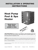
INSTALLATION & OPERATING INSTRUCTIONS Heat Pump Pool & Spa Heater Model Series 5350, 6350, 6350HC & 8350 NewPrRo-d4u1c0tA not attempt to install, service, or maintain this equipment. This manual should be maintained in legible condition and kept adjacent to the heat pump pool heater or in a safe - Rheem M5350ti | Installation Instructions - Page 2
Rev. 2 reflects the following: Additions: 3-phase wiring diagrams on pages 23 & 24, phone number on page 15 Changes to: Fig. 1 on page 7, Tables A & B on page 9, phone number on page 12, Fig. 6 on page 17, Fig. 7 on page 18 2 - Rheem M5350ti | Installation Instructions - Page 3
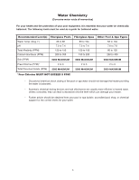
EXCEED 5 PPM! • Occasional chemical shock dosing of the pool or spa water should not damage the heater providing the water is balanced. • Automatic chemical dosing devices and salt chlorinators are usually more efficient in heated water. Unless controlled, they can lead to excessive chlorine level - Rheem M5350ti | Installation Instructions - Page 4
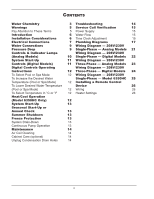
Spa Mode) 12 Installing a Remote Control To Lower Desired Water Temperature Device 26 (Pool or Spa Mode) 12 Wiring 26 To Select Temperature in °C or °F 12 Heater Settings 26 Heat/Cool Operation (Model 6350HC Only) 12 System Start-Up 13 Seasonal Start-Up or Annual Check 13 Summer - Rheem M5350ti | Installation Instructions - Page 5
or product or property damage if ignored. Indicates special instructions on installation, operation, or maintenance which are important but not related to personal injury hazards. This manual, as well as the pool/spa heat pump pool heater itself, contains ANSI-approved product safety signs and - Rheem M5350ti | Installation Instructions - Page 6
supporting base must be high enough to keep it completely free of standing water at all times. Situate the heat pump pool heater carefully to minimize installation costs while providing maximum efficiency of operation, and to allow adequate service access, as follows: • For unrestricted air intake - Rheem M5350ti | Installation Instructions - Page 7
HEATER 3 FT MIN 60" MIN AIR FLOW OUT 12" MIN AIR FLOW IN AIR FLOW IN Fig. 1: Installation Clearances • When installed in areas where freezing temperatures can be encountered, drain the water Article 680, for general requirements for swimming pools and equipment, and to Article 440 for - Rheem M5350ti | Installation Instructions - Page 8
8 MODEL A B 5350 38-1/2 2.90 6350 42-1/2 2.90 6350HC 42-1/2 2.90 8350 42-1/2 2.90 - Rheem M5350ti | Installation Instructions - Page 9
to the external control system's instructions, and page 26 of this manual, for installation information. the purpose and, in either case, should be at least equal in size to the main pool/spa circulation piping. Water Connections CAUTION: The heat pump pool heater inlet and outlet connections are - Rheem M5350ti | Installation Instructions - Page 10
the heat pump pool heater and will void the heat pump pool heater warranty. Controls & Indicator Lamps (Analog Models) Your analog heat pump pool heater incorporates safety controls and indicators to ensure its safe, reliable operation (for models with digital controls, see page 11). Water Pressure - Rheem M5350ti | Installation Instructions - Page 11
than the air entering the unit. If not, see the Troubleshooting Section. Controls (Digital Models) Your heat pump pool heater incorporates digital safety controls and indicators to ensure its safe, reliable operation (for models with analog controls, see page 10). Water Pressure Switch: Prevents - Rheem M5350ti | Installation Instructions - Page 12
Instructions Heat/Cool Operation (Model 6350HC Only) The electronic board has the capability of memorizing two different programmed temperature settings as follows (refer to Fig. 5): • For a pool, maximum 95°F (35°C) • For a spa, maximum 104°F (40°C) The heat/cool model is designed to both heat - Rheem M5350ti | Installation Instructions - Page 13
various component temperatures to normalize. 4. Verify that the discharge air temperature is approximately 8°-10°F cooler than the air entering the unit. If not, see the Troubleshooting Section. If you do not plan to use the heat pump pool heater during the summer months, secure and protect it as - Rheem M5350ti | Installation Instructions - Page 14
debris. 2. If condensation becomes a problem, optional drain pans are available from your heat pump pool heater distributor or pool dealer. • Is water condensing on the evaporator and internal copper pipes? This is also evidence of heat removal from the air. When the air is cool with low humidity - Rheem M5350ti | Installation Instructions - Page 15
models) on the not, then the thermostat setting is not higher than control panel still does not light, and water is circu- the temperature of the water. Raise the thermostat lating in the pool, verify that all valves are setting. positioned correctly. NOTE: The heat pump pool heater will - Rheem M5350ti | Installation Instructions - Page 16
control. The unit will show (LP3) after 3 LP faults and shuts down the unit and pool pump for protection. If this occurs, you should call for service. Low water flow in the unit or faulty high pressure control. Check water flow/backwash. The unit will show (HP3) after 3 HP faults. This will stop the - Rheem M5350ti | Installation Instructions - Page 17
CHEMICAL INTRODUCTION CHECK VALVE Plumbing Diagrams Fig. 6: For systems with pumps of less than 2 HP (under 80 gpm), no external bypass is required. Connections are 2-inch unions. Plumb the heat pump pool heater AFTER the filter and BEFORE any chlorinators. 17 FILTER WATER IN (FROM POOL OR SPA) - Rheem M5350ti | Installation Instructions - Page 18
VALVE FILTER WATER IN (FROM POOL OR SPA) Fig. 7: For systems with pumps of 2 HP or greater (over 80 gpm), an external bypass is required. Adjust the bypass valve to divert a minimum of 40 gpm through the heat pump pool heater. Connections are 2-inch unions. Plumb the heat pump pool heater AFTER - Rheem M5350ti | Installation Instructions - Page 19
Fig. 8: Pool Piping for Heat Pump Pool Heater and Gas Pool Heater 19 - Rheem M5350ti | Installation Instructions - Page 20
UNITS UNITS UNITS Fig. 9: Pool Piping for Heat Pump Pool Heaters, Multiple, Primary/Secondary 20 - Rheem M5350ti | Installation Instructions - Page 21
Models COIL [CONTACTOR, FAN RELAY] LED LEGEND TER. STRIP CAPACITOR LOW PRESSURE SWITCH HIGH PRESSURE SWITCH L E D'S A POWER AMBER COMPRESSOR CONTACTOR FAN RELAY B HEAT GREEN C WATER CONTROL. TO ENGAGE AN EXTERNAL CONTROL SYSTEM, PUT THE POOL-REMOTE-SPA SWITCH IN THE REMOTE POSITION. 21 - Rheem M5350ti | Installation Instructions - Page 22
Wiring Diagram 208V/230V Single-Phase Digital Models 22 - Rheem M5350ti | Installation Instructions - Page 23
Wiring Diagram - 208V/230V Three-Phase - Analog Models 23 - Rheem M5350ti | Installation Instructions - Page 24
Wiring Diagram 208V/230V Three-Phase Digital Models 24 - Rheem M5350ti | Installation Instructions - Page 25
Wiring Diagram 208V/230V Single-Phase Model 6350HC LEGEND COIL [CONTACTOR, FAN & POWER DEFROST] TER. STRIP CAPACITOR FAN RELAY LOW PRESSURE SWITCH HIGH PRESSURE SWITCH COMPRESSOR CONTACTOR REVERSING SOLENOID WATER PRESSURE SWITCH USE TERMINALS 21 & 22 TO ATTACH 2-WIRE CONTROL SYSTEMS THAT HAVE - Rheem M5350ti | Installation Instructions - Page 26
and POOL connections on the heat pump pool heater wiring block. For a 3-wire control, use the COMMON, SPA and POOL connections on the heat pump pool heater wiring block. Fig. 10: Heater Wiring Block - Analog Heaters Heater Settings Fig. 11: Heater Wiring Block - Digital Heaters Heater Settings - Rheem M5350ti | Installation Instructions - Page 27
27 - Rheem M5350ti | Installation Instructions - Page 28
Raypak, Inc., 2151 Eastman Avenue, Oxnard, CA 93030 (805) 278-5300 Fax (805) 278-5468 Heat Pump Service 1-800-260-2758 Litho in U.S.A. 28
-
 1
1 -
 2
2 -
 3
3 -
 4
4 -
 5
5 -
 6
6 -
 7
7 -
8
-
9
-
10
-
11
-
12
-
13
-
14
-
15
-
16
-
17
-
18
-
19
-
20
-
21
-
22
-
23
-
24
-
25
-
26
-
27
-
28
 |
 |
INSTALLATION & OPERATING
INSTRUCTIONS
Catalog No. RM6000.552A
Effective: 12-29-09
Replaces: 11-03-09
P/N 241380 Rev. 2
FOR YOUR SAFETY:
Do not store or use gasoline or other flammable vapors and
liquids or other combustible materials in the vicinity of this or any other appliance. To
do so may result in an explosion or fire.
Model Series
5350, 6350,
6350HC & 8350
Heat Pump
Pool & Spa
Heater
US
C
L
I
S
T
E
D
R
NOTE:
The instructions in this manual are for the use of qualified individuals specially trained and experienced
in the installation and maintenance of this type of equipment and related system components. Installation and
service personnel are required by some states to be licensed. Persons not qualified shall not attempt to install,
service, or maintain this equipment.
This manual should be maintained in legible condition and kept adjacent to the heat pump pool heater or in a
safe place for future use.
New R-410A
Product