Rheem M5350ti Installation Instructions - Page 17
Plumbing Diagrams - pool heater e
 |
View all Rheem M5350ti manuals
Add to My Manuals
Save this manual to your list of manuals |
Page 17 highlights
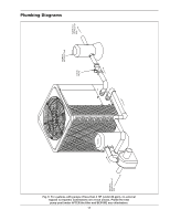
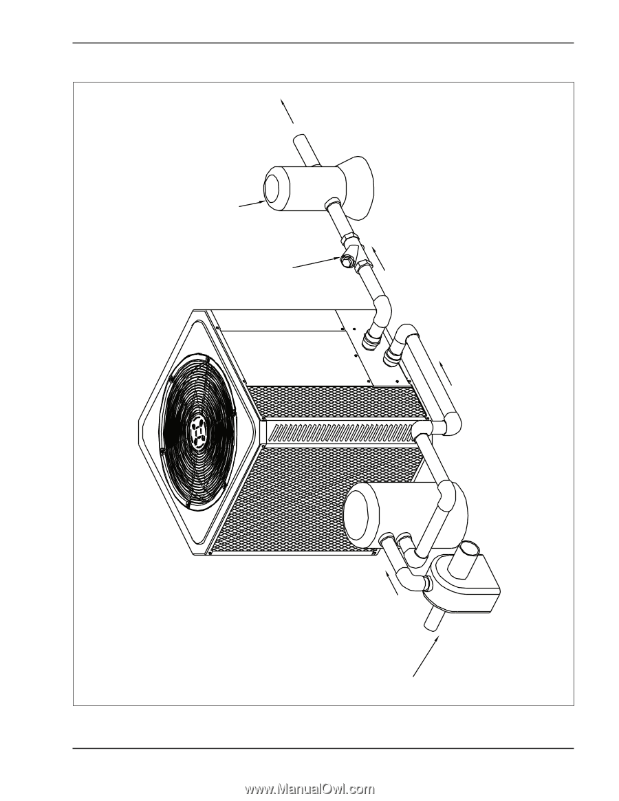
WATER OUT (TO POOL OR SPA) CHEMICAL INTRODUCTION CHECK VALVE Plumbing Diagrams Fig. 6: For systems with pumps of less than 2 HP (under 80 gpm), no external bypass is required. Connections are 2-inch unions. Plumb the heat pump pool heater AFTER the filter and BEFORE any chlorinators. 17 FILTER WATER IN (FROM POOL OR SPA)
-
 1
1 -
2
-
3
-
4
-
5
-
6
-
7
-
8
-
9
-
10
-
11
-
 12
12 -
 13
13 -
 14
14 -
 15
15 -
 16
16 -
 17
17 -
 18
18 -
 19
19 -
 20
20 -
 21
21 -
 22
22 -
23
-
24
-
25
-
26
-
27
-
28
 |
 |
17
Plumbing Diagrams
WATER IN
(FROM POOL OR
SPA)
FILTER
CHECK
VALVE
CHEMICAL
INTRODUCTION
WATER OUT
(TO POOL OR
SPA)
Fig. 6: For systems with pumps of less than 2 HP (under 80 gpm), no external
bypass is required. Connections are 2-inch unions. Plumb the heat
pump pool heater AFTER the filter and BEFORE any chlorinators.