Rheem P-M207 Operating Instructions - Page 40
Warning, Heat Exchanger Removal, Tube Cleaning Procedure, Desooting Procedure, Immersion Well
 |
View all Rheem P-M207 manuals
Add to My Manuals
Save this manual to your list of manuals |
Page 40 highlights
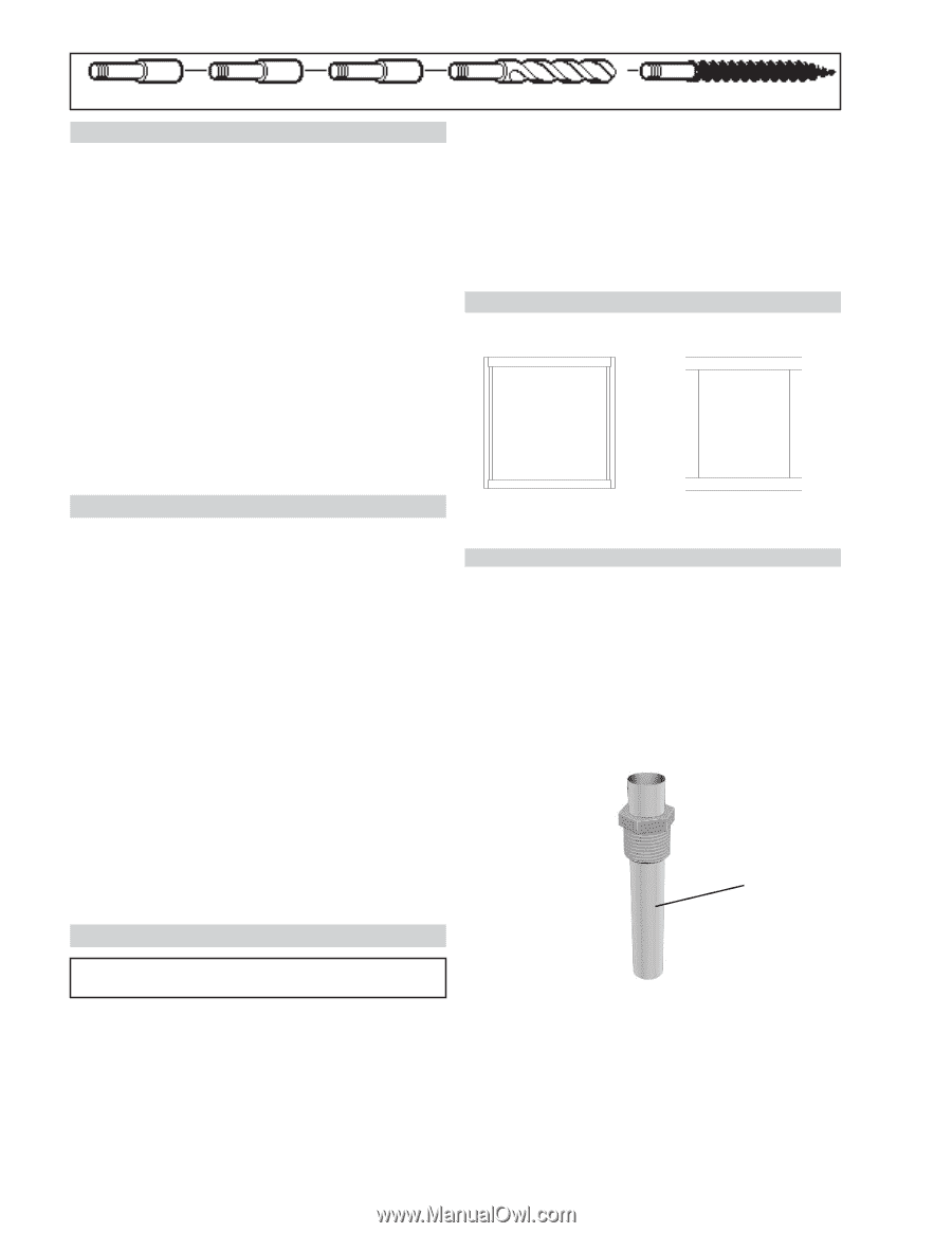
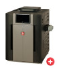
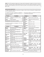
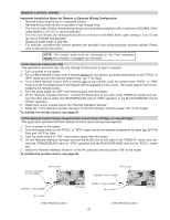
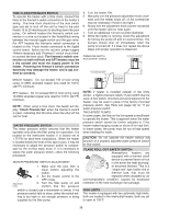
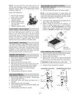
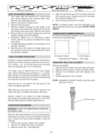
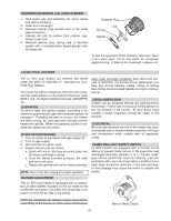
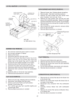
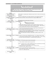
Extension Pieces (2) Auger with Carbide Tip Wire Brush HEAT EXCHANGER REMOVAL 1. Shut water, gas and electricity off, close valves and relieve pressure, then remove relief valve. Remove side inspection panels. 2. Remove top jacket holding screws. 3. Remove rear top panel. 4. Remove screws mounting the rain shield to the rear panel. Also remove the screws that mount the rain shield to the sway brace. Remove rain shield. 5. Remove the four (4) screws holding down the flue collector. Remove the flue collector. 6. Disconnect flange nuts on Inlet/Outlet header, loosen union(s) at gas pipe and slide heater away from piping. 7. Lift heat exchanger straight up using caution not to damage refractory. 8. Reverse above procedure to reinstall. Make sure the insulation strips are properly replaced on top of the refractory retainer. 4. Remove heat exchanger from the heater and wash with a garden hose, making sure soot is removed from spaces between fins. 5. Reverse above procedure to reinstall. NOTE: In extreme cases it may be necessary to do steam cleaning at the local car wash. DO NOT WIRE BRUSH. COMBUSTION CHAMBER REMOVAL To remove combustion chamber, you must first have removed the heat exchanger. TUBE CLEANING PROCEDURE Establish a regular inspection schedule, the frequency depending on the local water conditions and the severity of service. Do not let the tubes clog up solidly. Clean out deposits over 1/16" in thickness. The heater may be cleaned from the return header side, without breaking pipe connections. It is preferable, however, to remove both headers for better visibility through the tubes and to be sure the ground-up lime dust does not get into the system. Note that you do not remove the top panel or the heater exchanger, generally. Atmospheric Heaters Lo NOx Heaters REFRACTORY PANELS - TOP VIEW IMMERSION WELL REPLACEMENT (Millivolt and ASME) 1. Shut off water to heater and drain heat exchanger. 2. Remove access panel on water connection side. 3. Remove old immersion well with bushing and sleeve. 4. Install replacement well in header. NOTE: Installation in polymer header should be hand tight plus 1/2 turn. After reaming, mount the wire brush in place of the auger and clean out debris remaining in the tubes. Another method is to remove the heat exchanger, ream tubes and immerse heat exchanger in non-inhibited de-scale solvent for severe scale build-up. Well Assembly DESOOTING PROCEDURE WARNING: SOOT IS COMBUSTIBLE. EXERCISE EXTREME CARE. Soot will clog areas between fins and cause eventual tube failure. Any sign of soot at the base of the burners or around the outer jacket indicates a need for cleaning. 1. Remove top and flue collector from cabinet. 2. Remove "V" baffles from heat exchanger. 3. Remove burner tray. (See page 39). 40
-
 1
1 -
2
-
3
-
4
-
5
-
6
-
7
-
8
-
9
-
10
-
11
-
12
-
13
-
14
-
15
-
16
-
17
-
18
-
19
-
20
-
21
-
22
-
23
-
24
-
25
-
26
-
27
-
28
-
29
-
30
-
31
-
32
-
33
-
34
-
 35
35 -
 36
36 -
 37
37 -
 38
38 -
 39
39 -
 40
40 -
 41
41 -
 42
42 -
 43
43 -
 44
44 -
 45
45 -
46
-
47
-
48
-
49
-
50
-
51
-
52
-
53
-
54
-
55
-
56
 |
 |