Ryobi HJP002 Operation Manual - Page 7
Operation - drill
 |
View all Ryobi HJP002 manuals
Add to My Manuals
Save this manual to your list of manuals |
Page 7 highlights
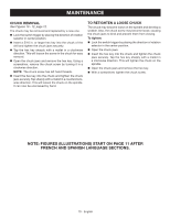
OPERATION WARNING: Do not allow familiarity with products to make you careless. Remember that a careless fraction of a second is sufficient to inflict serious injury. WARNING: Always wear eye protection marked to comply with ANSI Z87.1. Failure to do so could result in objects being thrown into your eyes resulting in possible serious injury. WARNING: Do not use any attachments or accessories not recommended by the manufacturer of this product. The use of attachments or accessories not recommended can result in serious personal injury. APPLICATIONS You may use this product for the purposes listed below: Drilling in all types of wood products (lumber, plywood, paneling, composition board, and hard board) Drilling in ceramics, plastics, fiberglass, and laminates Drilling in metals For complete charging instructions, refer to the Operator's Manual for the battery packs and chargers listed in the General Safety Rules. BATTERY PROTECTION FEATURES Ryobi lithium-ion batteries are designed with features that protect the lithium-ion cells and maximize battery life. If the tool stops during use, release the trigger to reset and resume operation. If the tool still does not work, the battery needs to be recharged. TO INSTALL BATTERY PACK See Figure 2, page 11. Place the direction of rotation selector in the center position. Insert the battery pack into the product as shown. Make sure the latches on each side of the battery pack snap in place and that battery pack is secured in the product before beginning operation. TO REMOVE BATTERY PACK Depress the latches on each side of the battery pack. Remove the battery pack from the tool. WARNING: Battery products are always in operating condition. Therefore, the switch should always be locked when not in use or carrying at your side. SWITCH TRIGGER See Figure 3, page 11. To turn the drill ON, depress the switch trigger. To turn it OFF, release the switch trigger. VARIABLE SPEED The switch trigger delivers higher speed with increased trigger pressure and lower speed with decreased trigger pressure. Note: You might hear a whistling or ringing noise from the switch during use. Do not be concerned; this is a normal part of the switch function. DIRECTION OF ROTATION SELECTOR (FORWARD/REVERSE/CENTER LOCK) See Figure 3, page 11. The direction of bit rotation is reversible and is controlled by a selector located above the switch trigger. With the drill held in normal operating position, the direction of rotation selector should be positioned to the left of the switch trigger for forward drilling. The drilling direction is reversed when the selector is to the right of the switch trigger. Setting the switch trigger in the OFF (center lock) position helps reduce the possibility of accidental starting when not in use. CAUTION: To prevent gear damage, always allow the chuck to come to a complete stop before changing the direction of rotation. To stop the drill, release the switch trigger and allow the chuck to come to a complete stop. NOTE: The drill will not run unless the direction of rotation selector is pushed fully to the left or right. Avoid running the drill at low speeds for extended periods of time. Running at low speeds under constant usage may cause the drill to become overheated. If this occurs, cool the drill by running it without a load and at full speed. KEYLESS CHUCK See Figure 4, page 11. The drill has a keyless chuck to tighten or release drill bits in the chuck jaws. The arrows on the chuck indicate which direction to rotate the chuck body in order to LOCK (tighten) or UNLOCK (release) the drill bit. 7 - English
-
 1
1 -
 2
2 -
 3
3 -
 4
4 -
 5
5 -
 6
6 -
 7
7 -
 8
8 -
 9
9 -
 10
10 -
 11
11 -
 12
12 -
13
-
14
-
15
-
16
-
17
-
18
-
19
-
20
-
21
-
22
-
23
-
24
-
25
-
26
-
27
-
28
-
29
-
30
-
31
-
32
 |
 |