Ryobi P1834 Operation Manual - Page 6
Assembly, Features, Operation
 |
View all Ryobi P1834 manuals
Add to My Manuals
Save this manual to your list of manuals |
Page 6 highlights
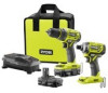
FEATURES PRODUCT SPECIFICATIONS Coupler 1/4 in. No Load Speed 0-2,900 /min. (RPM) Torque 2,000 in.lbs. Impacts Per Minute 3,800 IPM ASSEMBLY WARNING: Do not use this product if it is not completely assembled or if any parts appear to be missing or damaged. Use of a product that is not properly and completely assembled or with damaged or missing parts could result in serious personal injury. WARNING: Do not attempt to modify this product or create accessories or attachments not recommended for use with this product. Any such alteration or modification is misuse and could result in a hazardous condition leading to possible serious personal injury. If any parts are damaged or missing, please call 1-800-525-2579 for assistance. OPERATION WARNING: Do not allow familiarity with this product to make you careless. Remember that a careless fraction of a second is sufficient to inflict serious injury. WARNING: Always remove battery pack from the tool when you are assembling parts, making adjustments, cleaning, or when not in use. Removing battery pack will prevent accidental starting that could cause serious personal injury. WARNING: Always wear eye protection with side shields marked to comply with ANSI Z87.1, along with hearing protection. Failure to do so could result in objects being thrown into your eyes and other possible serious injuries. WARNING: Do not use any attachments or accessories not recommended by the manufacturer of this product. The use of attachments or accessories not recommended can result in serious personal injury. APPLICATIONS You may use this product for the purposes listed below: Driving long deck screws, driving carriage bolts into deck posts; driving Tapcon® screws into block walls and concrete; driving screws into metal studs VARIABLE SPEED SWITCH TRIGGER See Figure 1, page 9. The variable speed switch trigger delivers higher speed with increased trigger pressure and lower speed with decreased trigger pressure. To turn the tool ON, depress the switch trigger. To turn it OFF, release the switch trigger and allow the tool to come to a complete stop. DIRECTION OF ROTATION SELECTOR (FORWARD/REVERSE/CENTER LOCK) See Figure 1, page 9. Set the direction of rotation selector in the OFF (center lock) position to lock the switch trigger and help prevent accidental starting when not in use. Position the direction of rotation selector to the left of the switch trigger for forward operation. Position the selector to the right of the switch trigger to reverse the direction. NOTE: The tool will not run unless the direction of rotation selector is pushed fully to the left or right. NOTICE: To prevent gear damage, always allow the chuck to come to a complete stop before changing the direction of rotation. 6 - English
-
 1
1 -
 2
2 -
 3
3 -
 4
4 -
 5
5 -
 6
6 -
 7
7 -
 8
8 -
 9
9 -
 10
10 -
 11
11 -
 12
12 -
13
-
14
-
15
-
16
-
17
-
18
-
19
-
20
-
21
-
22
-
23
-
24
 |
 |
