Ryobi P20015BTLVNM Parts Diagram - Page 5
Parts List - B
 |
View all Ryobi P20015BTLVNM manuals
Add to My Manuals
Save this manual to your list of manuals |
Page 5 highlights
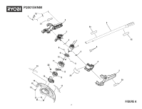
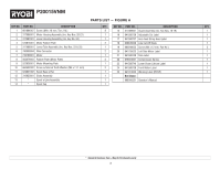
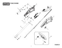
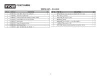
P20015VNM PARTS LIST - FIGURE B KEY NO. PART NO. DESCRIPTION QTY. KEY NO. PART NO. DESCRIPTION QTY. 1 661817001 Screw (M4 x 18 mm, Torx Socket Hd.) 13 9 660502002 Screw w/Internal Tooth Washer (M5 x 10.5 mm) 2 2 313289002 Handle Housing Assembly 1 10 541911001 Lock Ring 1 3 313290001 Switch, Contact Plate Assembly, and Wire Harness 1 11 940657185 Warning Icon Label 1 4 351183001 Switch Trigger and Lock-Out Assembly 1 12 696008001 Spring 1 5 541909001 Rotate Button 1 13 660643009 Screw (1/4-20 x 45 mm, Hex Cap Hd.) 1 6 679973001 Trigger Compression Spring 1 14 518949001 Wing Nut (1/4-20) 1 7 523001003 Wire Pressure Plate 1 15 308991006 Auxiliary Handle Assembly (Inc. Key Nos. 13-14) 1 8 317079001 Upper Tube Assembly (Inc. Key No. 11) 1 5
-
 1
1 -
 2
2 -
 3
3 -
 4
4 -
 5
5 -
 6
6
 |
 |

5
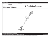
P20015VNM
PARTS LIST — FIGURE B
KEY NO.
PART NO.
DESCRIPTION
QTY.
9
660502002
Screw
w/Internal Tooth Washer (M5 x 10.5 mm)
2
10
541911001
Lock Ring
1
11
940657185
Warning Icon Label
1
12
696008001
Spring
1
13
660643009
Screw (1/4-20 x 45 mm, Hex Cap Hd.)
1
14
518949001
Wing Nut (1/4-20)
1
15
308991006
Auxiliary Handle Assembly (Inc. Key Nos. 13-14)
1
KEY NO.
PART NO.
DESCRIPTION
QTY.
1
661817001
Screw (M4 x 18 mm, Torx Socket Hd.)
13
2
313289002
Handle Housing Assembly
1
3
313290001
Switch, Contact Plate Assembly, and Wire Harness
1
4
351183001
Switch Trigger and Lock-Out Assembly
1
5
541909001
Rotate Button
1
6
679973001
Trigger Compression Spring
1
7
523001003
Wire Pressure Plate
1
8
317079001
Upper Tube Assembly (Inc. Key No. 11)
1