Ryobi P553 Operation Manual - Page 13
Installing The Miter Lock Knob, Locking / Unlocking The Saw Arm, Installing The Rear Bracket,
 |
View all Ryobi P553 manuals
Add to My Manuals
Save this manual to your list of manuals |
Page 13 highlights
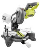
ASSEMBLY INSTALLING THE MITER LOCK KNOB See Figure 7. To install the miter lock knob, place the threaded stud on the end of the miter lock knob into the threaded hole in the control arm. Turn clockwise to tighten. LOCKING / UNLOCKING THE SAW ARM See Figure 7. To unlock and raise the saw arm: Firmly grasp the "D" handle and apply downward pressure while at the same time pulling the lock pin out and away from the saw housing. Release the lock pin and slowly raise the saw arm. To lock the saw arm: Firmly grasp the "D" handle and apply downward pressure while at the same time pushing the lock pin in and toward the saw housing. Release the lock pin allowing it to lock the saw into place. INSTALLING THE REAR BRACKET See Figure 8. "D" HANDLE LOCK PIN CONTROL ARM MITER LOCK KNOB Fig. 7 WARNING: A rear bracket is included with this miter saw to prevent tipping if the saw arm is released suddenly. Do not use this saw before installing the rear bracket and securely mounting the saw to a work surface or stand. Remove the screws from the Rear Bracket and set aside. Slide the bracket in the openings on the saw base, aligning the holes underneath the base with the holes in the bracket. Insert the screws into the holes and tighten securely. INSTALLING THE BEVEL LOCK KNOB See Figure 8. WASHER BLADE WRENCH STORAGE SCREW REAR BRACKET BEVEL LOCK KNOB Fig. 8 EXHAUST PORT To install the bevel lock knob, slide the washer onto the threaded stud on the end of the bevel lock knob then place the knob into the threaded hole on the back of the saw. Turn clockwise to tighten. DUST BAG BLADE WRENCH See Figure 8. A blade wrench is included with this saw. One end of the wrench is a phillips screwdriver and the other end is a hex Fig 9 key. Use the hex key end when installing or removing blade and the phillips end when removing or loosening screws. A storage area for the blade wrench is located on the back of the left miter fence. DUST BAG See Figure 9. A dust bag is provided for use on this miter saw. It fits over the exhaust port on the upper blade guard. To install, squeeze the two metal clips to open the mouth of the bag and slide it on the exhaust port. Release the clips. The metal ring in the bag should lock in between the grooves on the exhaust port. To remove the dust bag for emptying, simply reverse the above procedure. 13 - English
-
 1
1 -
2
-
3
-
4
-
5
-
6
-
7
-
 8
8 -
 9
9 -
 10
10 -
 11
11 -
 12
12 -
 13
13 -
 14
14 -
 15
15 -
 16
16 -
 17
17 -
 18
18 -
19
-
20
-
21
-
22
-
23
-
24
-
25
-
26
-
27
-
28
-
29
-
30
-
31
-
32
-
33
-
34
-
35
-
36
-
37
-
38
-
39
-
40
-
41
-
42
-
43
-
44
-
45
-
46
-
47
-
48
-
49
-
50
-
51
-
52
-
53
-
54
-
55
-
56
-
57
-
58
-
59
-
60
-
61
-
62
-
63
-
64
-
65
-
66
-
67
-
68
-
69
-
70
-
71
-
72
-
73
-
74
-
75
-
76
-
77
-
78
-
79
-
80
-
81
-
82
-
83
-
84
 |
 |
