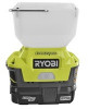
Ryobi P784K Operation Manual 1 - Page 9
Caution, Warning
 |
View all Ryobi P784K manuals
Add to My Manuals
Save this manual to your list of manuals |
Page 9 highlights
OPERATION SWITCH See Figure 4. Your drill starts and stops by depressing and releasing the switch trigger. Release the switch trigger to turn drill OFF. VARIABLE SPEED See Figure 4. Your drill has a variable speed feature in the switch. The switch delivers higher speed and torque with increased trigger pressure. Speed is controlled by the amount of switch trigger depression. SWITCH LOCK See Figure 4. The switch trigger can be locked in the OFF position. This feature helps reduce the possibility of accidental starting when not in use. To lock the switch trigger, place the direction of rotation selector in the center position. REVERSIBLE See Figure 4. This tool is reversible. The direction of rotation is controlled by a selector located above the switch trigger. With the drill held in normal operating position, the direction of rotation selector should be positioned to the left of the switch for drilling. The drilling direction is reversed when the selector is to the right of the switch. When the selector is in center position, the switch trigger is locked. CAUTION: To prevent gear damage, always allow chuck to come to a complete stop before changing the direction of rotation. To stop, release switch trigger and allow the chuck to come to a complete stop. WARNING: Battery tools are always in operating condition. Therefore, switch should always be locked when not in use or when carrying at your side. DIRECTION OF ROTATION SELECTOR REVERSE 5 20 24 24 SWITCH CENTER POSITION (LOCK) FORWARD TRIGGER Fig. 4 LO (1) SPEED HI (2) SPEED 5 20 TWO SPEED GEAR TRAIN (HI-LO) Fig. 5 TWO SPEED GEAR TRAIN See Figure 5. Your drill has a two-speed gear train designed for drilling or driving at LO (1) or HI (2) speeds. A slide switch is located on top of your drill to select either LO (1) or HI (2) speed. When using drill in the LO (1) speed range, speed will decrease and unit will have more power and torque. When using drill in the HI (2) speed range, speed will increase and unit will have less power and torque. Use LO (1) speed for high power and torque applications and HI (2) speed for fast drilling or driving applications. Page 9
-
 1
1 -
2
-
3
-
 4
4 -
 5
5 -
 6
6 -
 7
7 -
 8
8 -
 9
9 -
 10
10 -
 11
11 -
 12
12 -
 13
13 -
 14
14 -
15
-
16
 |
 |
