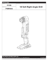
Ryobi PSBRA02B Parts Diagram - Page 2
Psbra02
 |
View all Ryobi PSBRA02B manuals
Add to My Manuals
Save this manual to your list of manuals |
Page 2 highlights
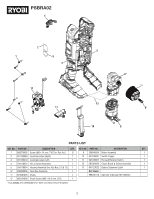
PSBRA02 4 2 1 3 5 12 11 5 6* 7* 13 8* 10 9 PARTS LIST KEY NO. PART NO. DESCRIPTION QTY. KEY NO. PART NO. DESCRIPTION QTY. 1 660570005 Screw (M3 x 14 mm, T10 Torx Pan Hd.) 8 9 206940004 Motor Assembly 1 2 941120580 Icon/Data Label (Right) 1 10 541246001 Switch Trigger 1 3 941120579 Icon/Data Label (Left) 1 11 541245001 Forward/Reverse Switch 1 4 204118023 Hi-Lo Switch Assembly 1 12 281084002 Circuit Board & Switch Assembly 1 5 204118024 Housing Assembly (Inc. Key Nos. 2-3 & 13) 1 13 941123032 Battery Statement Label 1 6* 206940006 Gear Box Assembly 1 Not Shown: 7* 674081003 Chuck 1 998000178 Operator's Manual (961153365) 8* 660134006 Chuck Screw (M6 x 18.5 mm, LHT) 1 *Tools BEFORE S/N: CS20303N670137-0422 must replace keys 6-8 together. 2
-
 1
1 -
 2
2 -
 3
3
 |
 |

2
PSBRA02
6*
5
5
7*
4
12
11
10
9
8*
1
13
2
3
KEY NO.
PART NO.
DESCRIPTION
QTY.
1
660570005
Screw (M3 x 14 mm, T10 Torx Pan Hd.)
8
2
941120580
Icon/Data Label (Right)
1
3
941120579
Icon/Data Label (Left)
1
4
204118023
Hi-Lo Switch Assembly
1
5
204118024
Housing Assembly (Inc. Key Nos. 2-3 & 13)
1
6*
206940006
Gear Box Assembly
1
7*
674081003
Chuck
1
8*
660134006
Chuck Screw (M6 x 18.5 mm, LHT)
1
PARTS LIST
KEY NO.
PART NO.
DESCRIPTION
QTY.
9
206940004
Motor Assembly
1
10
541246001
Switch Trigger
1
11
541245001
Forward/Reverse Switch
1
12
281084002
Circuit Board & Switch Assembly
1
13
941123032
Battery Statement Label
1
Not Shown:
998000178
Operator’s Manual (961153365)
*Tools BEFORE S/N: CS20303N670137-0422 must replace keys 6-8 together.