Ryobi R163K English Manual - Page 10
Operation - 1 2 collet
 |
View all Ryobi R163K manuals
Add to My Manuals
Save this manual to your list of manuals |
Page 10 highlights
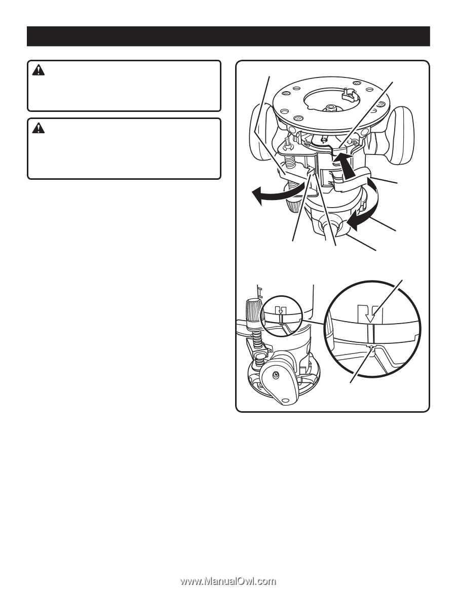
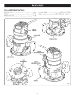
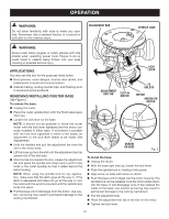
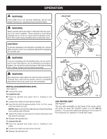
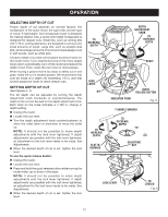
OPERATION WARNING: Do not allow familiarity with tools to make you careless. Remember that a careless fraction of a second is sufficient to inflict serious injury. ADJUSTMENT BAR SPINDLE LOCK WARNING: Always wear safety goggles or safety glasses with side shields when operating power tools. Failure to do so could result in objects being thrown into your eyes resulting in possible serious injury. APPLICATIONS You may use this tool for the purposes listed below: n Rout grooves, carve designs, mortise door jambs, and create joints in wood and wood products n Cabinet making, routing counter tops, and finishing work in wood and wood products REMOVING/INSTALLING ROUTER BASE See Figure 2. To remove the base: n Unplug the router. n Place the router upside down with the Ryobi label away from you. n Loosen the lock lever on the base. Note: It should not be possible to move the router motor with the lock lever tightened and the motor correctly installed in either base. If movement is possible with the lock lever tightened in either of the bases, an adjustment to the lock lever needs to be made. See Adjustments. n Hold the handles and pull the adjustment bar from the slot in the motor base. n Lift the base up from the slot until the adjustment bar tab passes out of the slot area. n After the tab has cleared the slot, release the adjustment bar and press the spindle lock down and in (until it fully locks in the collet spindle) so that it slides behind the base housing. NOTE: When using the spindle lock for any application, make sure that the latch goes all the way in. If the latch is depressed and does not go all the way in, turn the collet with the wrench provided until the spindle lock locks into place. n Pull the base until it dislodges from the motor. Use caution, as forcing may result in permanent damage to the locking mechanism. LOCK LEVER ADJUSTMENT BAR TAB SLOT IN MOTOR TO UNLOCK MOTOR ARROW ON MOTOR ARROW ON BASE Fig. 2 To install the base: n Unplug the router. n With the base right side up, loosen the lock lever. n Push the spindle lock in, holding it into place. n Align arrow on base with arrow on motor. n Push the base until it lodges into the motor housing. The spindle lock can be released once the motor slides down into the base. It will disengage once it has cleared the inside of the base. Use caution as forcing may result in permanent damage to the locking mechanism. n Pull the adjustment bar. n Place the adjustment bar tab in the slot on the motor. n Tighten the lock lever. 10
-
 1
1 -
2
-
3
-
4
-
 5
5 -
 6
6 -
 7
7 -
 8
8 -
 9
9 -
 10
10 -
 11
11 -
 12
12 -
 13
13 -
 14
14 -
 15
15 -
16
-
17
-
18
-
19
-
20
 |
 |