Ryobi RTS10 English Manual - Page 16
Assembly - saw
 |
View all Ryobi RTS10 manuals
Add to My Manuals
Save this manual to your list of manuals |
Page 16 highlights
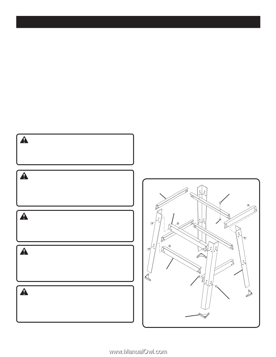
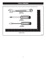
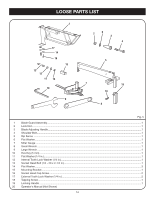
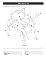
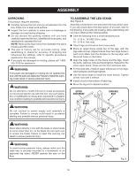
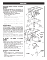
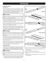
ASSEMBLY UNPACKING This product requires assembly. Carefully remove the tool and any accessories from the box. Place it on a level work surface. Inspect the tool carefully to make sure no breakage or damage occurred during shipping. Do not discard the packing material until you have carefully inspected the tool, identified all loose parts, and satisfactorily operated the tool. NOTE: Remove the foam block from between the saw's housing and the motor. The saw is factory set for accurate cutting. After assembling it, check for accuracy. If shipping has influenced the settings, refer to specific procedures explained in this manual. If any parts are damaged or missing, please call 1-800525-2579 for assistance. WARNING: If any parts are damaged or missing do not operate this tool until the parts are replaced. Failure to heed this warning could result in serious personal injury. WARNING: Do not attempt to modify this tool or create accessories not recommended for use with this tool. Any such alteration or modification is misuse and could result in a hazardous condition leading to possible serious personal injury. WARNING: Do not connect to power supply until assembly is complete. Failure to comply could result in accidental starting and possible serious personal injury. TO ASSEMBLE THE LEG STAND See Figure 6. Assembly is best done in the area where the saw will be used. If you are unsure about the description of any part, refer to the drawing. If any parts are missing, delay assembling until you have obtained the missing part(s). Take the following from a small hardware pack: 16 - 5/16 in. 18-UNC 5/8 in. bolts 16 - 5/16 in. hex nuts Take 4 legs and 8 braces from loose parts. Place an upper brace inside two of the legs, with the legs wide end up. (Upper braces have two large holes in each end.) Make sure the dimples on the leg align with the small holes on the brace. Align the large holes on the brace and the legs. Insert the bolts. Add hex nuts and hand tighten. Repeat for the other upper brace. These are the front and back sets. For the side sets, install an upper side brace on two legs. Add hardware and finger tighten. Use the same steps to install the lower braces. Tighten all hex nuts with a wrench. Install a foot to the bottom of each leg. Move the leg set to desired location. upper Side brace CARRIAGE Bolt upper brace Hex Nut WARNING: Never stand directly in line with the blade or allow hands to come closer than 3 in. to the blade. Do not reach over or across the blade. Failure to heed this warning can result in serious personal injury. WARNING: To avoid serious personal injury, always make sure the table saw is securely mounted to a workbench or an approved leg stand. NEVER operate the saw on the floor. Lower Brace hex nut foot LEG carriage bolt Fig. 6 16
-
 1
1 -
2
-
3
-
4
-
5
-
6
-
7
-
8
-
9
-
10
-
 11
11 -
 12
12 -
 13
13 -
 14
14 -
 15
15 -
 16
16 -
 17
17 -
 18
18 -
 19
19 -
 20
20 -
 21
21 -
22
-
23
-
24
-
25
-
26
-
27
-
28
-
29
-
30
-
31
-
32
-
33
-
34
 |
 |