Ryobi RTS20 English Manual - Page 26
Heeling Paralleling The Blade To The, Miter Gauge Groove, Warning
 |
View all Ryobi RTS20 manuals
Add to My Manuals
Save this manual to your list of manuals |
Page 26 highlights
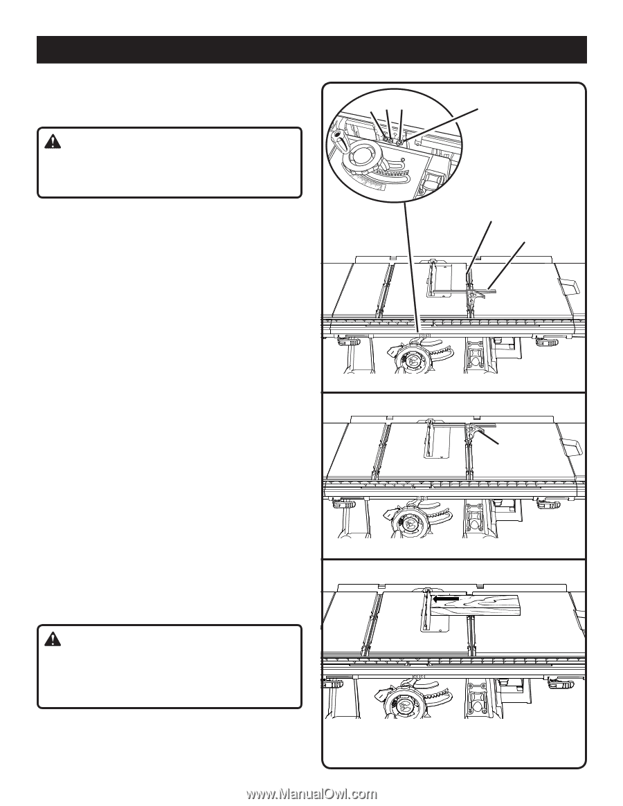
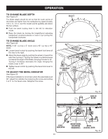
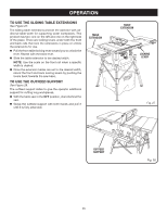
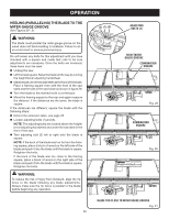
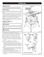
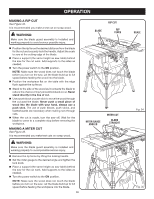
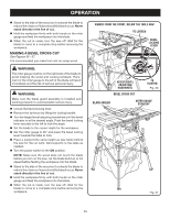
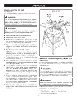
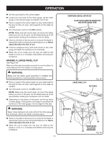
operation heeling (paralleling) the blade to the miter gauge groove See Figures 29 - 31. WARNING: The blade must parallel the miter gauge groove so the wood does not bind resulting in kickback. Failure to do so could result in serious personal injury. Do not loosen any bolts for this adjustment until you have checked with a square and made test cuts to be sure adjustments are necessary. Once the bolts are loosened, these items must be reset. Unplug the saw. Lift the blade guard. Raise the blade all the way by turning the height/bevel adjusting handwheel. Mark beside one of the blade teeth at the front of the blade. Place a framing square even with the front of the saw table and the side of the saw blade as shown in figure 29. Turn the blade so the marked tooth is at the back. Move the framing square to the rear and again measure the distance. If the distances are the same, the blade is square. If the distances are different, square the blade with the following steps: Extend the extension table, see page 25. Loosen adjusting bolts (1) and (3). NOTE: The adjusting bolts are located above the height/ bevel adjusting handwheel and under the saw table in the front of the saw. Turn adjusting bolt (2) left or right until the blade is square. NOTE: If the back of the blade was too far from the framing square, place a block of wood on the left side of the blade and push it into the blade until the blade is square. Retighten the bolts. If the back of the blade was too close to the framing square, place a block of wood on the right side of the blade and push it into the blade until the blade is square. Retighten the bolts. WARNING: To reduce the risk of injury from kickback, align the rip fence to the blade following any blade adjustments. Always make sure the rip fence is parallel to the blade before beginning any operation. (2) (1) (3) adjusting bolts (3) RIGHT MITER gauge GROOVE COMBINATION SQUARE Fig. 29 COMBINATION SQUARE Fig. 30 BLADE TOO CLOSE TO MITER GAUGE GROOVE Fig. 31 26
-
 1
1 -
2
-
3
-
4
-
5
-
6
-
7
-
8
-
9
-
10
-
11
-
12
-
13
-
14
-
15
-
16
-
17
-
18
-
19
-
20
-
 21
21 -
 22
22 -
 23
23 -
 24
24 -
 25
25 -
 26
26 -
 27
27 -
 28
28 -
 29
29 -
 30
30 -
 31
31 -
32
-
33
-
34
-
35
-
36
-
37
-
38
-
39
-
40
 |
 |