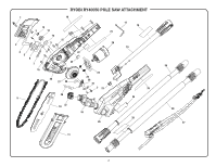
Ryobi RY40550 Parts Diagram - Page 3
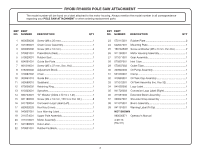
Pole Saw Attachment, Key Part, No. Number, Description, Not Shown
 |
View all Ryobi RY40550 manuals
Add to My Manuals
Save this manual to your list of manuals |
Page 3 highlights
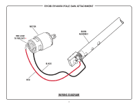
RYOBI RY40050 POLE SAW ATTACHMENT The model number will be found on a label attached to the motor housing. Always mention the model number in all correspondence regarding your POLE SAW ATTACHMENT or when ordering replacement parts. KEY PART NO. NUMBER DESCRIPTION QTY 1 660058008 Screw (M6 x 25 mm 1 2 551066001 Chain Cover Assembly 1 3 660005006 Screw (M3 x 10 mm 4 4 570821001 Press Block (Seal 1 5 570820001 Rubber Seal 1 6 634561001 Guide Bar Plate 1 7 661816001 Screw (M5 x 37 mm, Soc. Hd 1 8 678356002 Adjustment Block 1 9 310987002 Chain 1 10 300961010 Guide Bar 1 11 580699010 Scabbard 1 12 670608002 Retaining Ring 1 13 610323001 Sprocket 1 14 690733001 "D" Washer (OD24 x ID 10 x 1.2t 1 15 661189003 Screw (M4 x 18 mm, T20 Torx Pan Hd 8 16 941720004 Connexion Logo Label (Left 1 17 680002003 Hex Key (5 mm 1 18 940657061 Icon Warning Label 1 19 311074001 Upper Pole Assembly 1 20 311070001 Motor Assembly 1 21 941588023 Data Label 1 22 570831001 Rubber Fix Block 1 KEY PART NO. NUMBER DESCRIPTION QTY 23 570115001 Rubber Plate 2 24 642037001 Mounting Plate 1 25 T661845001 Screw w/Washer (M5 x 9 mm, Pan Hd 2 26 311180001 Motor Housing Assembly 1 27 311071001 Gear Assembly 1 28 570807001 Inlet Tube 1 29 570807002 Outlet Tube 1 30 300946002 Oil Pump Assembly 1 31 531003001 Clamp 1 32 310983001 Oil Tank Cap Assembly 1 33 311072001 Oil Tank Assemlby (Inc. Key 32 1 34 941655006 Logo Label 1 35 941720003 Connexion Logo Label (Right 1 36 311081002 Extended Boom Assembly 1 37 308047001 Shoulder Strap Assembly 1 38 311075001 Boom Assembly 1 39 941791001 Warning Label (Fr/Sp 1 NOT SHOWN 990000371 Operator's Manual 4-29-13 (Rev:01) 3
-
 1
1 -
 2
2 -
 3
3 -
 4
4
 |
 |
