Samsung 305T Service Manual
Samsung 305T - SyncMaster - 30" LCD Monitor Manual
 |
UPC - 729507700151
View all Samsung 305T manuals
Add to My Manuals
Save this manual to your list of manuals |
Samsung 305T manual content summary:
- Samsung 305T | Service Manual - Page 1
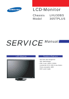
LCD-Monitor Chassis LHU30BS Model 305TPLUS SERVICE Manual LCD Monitor Fashion Feature - Back Side cable management - Silm / Narrow Design - PCB: 2 Layer, 150mm x 100mm - Connectivity: DVI-D, USB 2.0 (1up, 4down) - Power consumption: 130W - Built in power supply - Samsung 305T | Service Manual - Page 2
-This Service Manual is a property of Samsung Electronics Co., Ltd. Any unauthorized use of Manual can be punished under applicable International and/or domestic law. Samsung Electronics Co.,Ltd. 416, Maetan-3Dong, Yeongtong-Gu, Suwon City, Gyeonggi-Do, Korea, 443-742 Printed in Korea P/N : BN82- - Samsung 305T | Service Manual - Page 3
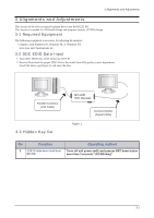
is necessary for adjusting the monitor: Computer with Windows 95, Windows 98, or Windows NT. MTI-2055 DDC MANAGER JIG 3-2 DDC EDID Data Input 1. Input DDC EDID data when replacing AD PCB. 2. Receive/Download the proper DDC file for the model from HQ quality control department. Install the below jig - Samsung 305T | Service Manual - Page 4
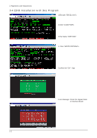
3 Alignments and Adjustments 3-4 EDID Installation with Dos Program 1.Execute "DDC21.exe"± 2.Click "LOAD FILE"± 3.File Name "305T.DDC" 4. Click "WRITE EEPROM"± Confirm the "OK" Sign Error Massage: Check the Signal Cable or Interface Board 3-2 - Samsung 305T | Service Manual - Page 5
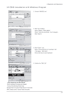
't change"± Click "Save"± 3. Click "Open" icon. Select "Connected Port #1" and Next "OK". * File Name - 305T.DDC Press enter key on your keyboard. 4. Confirm the "DDC OK". - After Replacing the Main Board -EDID Installation (Analog and Digital) -Factory Reset(Using Power key) During Power off, press - Samsung 305T | Service Manual - Page 6
3 Alignments and Adjustments Memo 3-4 - Samsung 305T | Service Manual - Page 7
7 Block Diagram 7-1 Block Diagram (Main) 7 Block Diagrams 7-1 - Samsung 305T | Service Manual - Page 8
7 Block Diagrams 7-2 Block Diagram (SMPS) 7-2 - Samsung 305T | Service Manual - Page 9
13 Circuit Descriptions 13-1 BLOCK discription (MAIN) 13 Circuit Descriptions 13-1 - Samsung 305T | Service Manual - Page 10
BOX,30P,1R,1.25mm,SMD-A,Sn+Pb,IVR 8 DATA CN_S_015_G2, CONNECTOR-HEADER, BOX,15P,1R,1.25mm,SMD-A,SnPb,IVR CONNECTOR 9 POWER CN_S_016, HEADER-BOARD TO CABLE, BOX,16P,1R,2mm,ANGLE,SN,IVORY CONNECTOR 10 FUNCTION CN_S_006_G2, CONNECTOR-HEADER, BOX,6P,1R,1.25mm,SMD-A,SnPb,IVR CONNECTOR 11 - Samsung 305T | Service Manual - Page 11
13-2 BLOCK discription (SMPS) 13 Circuit Descriptions 13-3 - Samsung 305T | Service Manual - Page 12
13 Circuit Descriptions No BLOCK DESCRIPTION 1 EMI Filter Coil Line filter NAME LX801s 2 Inrush current For continued protection FP801S 3 PFC section Power Factor Correction (PFC) allows power distribution to operate at its maximum efficiency PFC - Samsung 305T | Service Manual - Page 13
This section of the service manual describes the disassembly and reassembly procedures for the 305TLCD monitor. WARNING: This monitor contains electrostatically sensitive devices. Use caution when handling these components. 11-1 Disassembly Cautions: 1. Disconnect the monitor from the power source - Samsung 305T | Service Manual - Page 14
11 Disassembly and Reassembly Description 3. Disconnect cables and remove the inverter power and function cable Picture Description 4. Remove 1screws from the Shield. 5. Remove 4screws from the Shield between LCD_psanel and Shield 6. Disconnect cables LVDS and Signal from Panel control board 11 - Samsung 305T | Service Manual - Page 15
Description 7. Remove 2screws from DVI input connector 11 Disassembly and Reassembly Picture Description 8. Up and down the chassis ass'y 9. Remove 2 screw on the main board 10.Remove 3 screws on the SMPS board 11-3 - Samsung 305T | Service Manual - Page 16
11 Disassembly and Reassembly Description 11.Disconnect cables LVDS and Signal and Power from Main board Picture Description 11-3 Reassembly Reassembly procedures are in the reverse order of disassembly procedures. 11-4 - Samsung 305T | Service Manual - Page 17
(305T PLUS),HIPS HB KNOB-CONTROL;HUBBLE,HIPS HB,T2.0,UT-0510 KNOB-DECORATION;HUBBLE,ABS HB,T2.0,NATUR ASSY BOARD P-FUNCTION;HUBBLE,SJ06-01-013 HOLDER-CARE;PJT,ACRYL-FOAM,T0.25,W30.0mm 0.1 M0002 BN90-01015A ..2 M0013 BN96-03991A ...3 M0006 BN63-02664A ASSY COVER REAR;LS30HUBCB/XAA ASSY - Samsung 305T | Service Manual - Page 18
6 Electrical Parts List Level Loc. No. Code No. ...3 CN802 3722-001414 ...3 T0174 BN97-01026Z ....4 000070 ....4 R110 2007-000070 ....4 R110 2007-000070 ....4 R110 2007-000070 Description & Specification JACK-USB;4P/2C,AUF,BLK,ANGLE,A TYPE ASSY SMD;LS30HUB* SOLDER-CREAM;LST309-M,-, - Samsung 305T | Service Manual - Page 19
....4 R110 2007-000074 Description & Specification R-CHIP;0ohm,5%,1/10W,TP,1608 10W,TP,1608 R-CHIP;100ohm,5%,1/10W,TP,1608 R-CHIP;100ohm,5%,1/10W,TP,1608 R-CHIP;100ohm,5%,1/10W,TP,1608 R-CHIP;100ohm,5%,1/10W,TP,1608 6 Electrical Parts List Q'ty 1 1 1 1 1 1 1 1 1 1 1 1 1 1 1 1 1 1 1 1 1 1 1 1 - Samsung 305T | Service Manual - Page 20
6 Electrical Parts List Level Loc. No. Code No. ....4 R110 2007-000074 ....4 R110 2007-000074 ....4 R110 2007-000084 ....4 R110 2007-000084 ....4 R110 2007-000084 Description & Specification R-CHIP;100ohm,5%,1/10W,TP,1608 R-CHIP;100ohm,5%,1/10W,TP,1608 R-CHIP;100ohm,5%,1/10W - Samsung 305T | Service Manual - Page 21
....4 C120 2203-000426 Description & Specification R-CHIP;4.7Kohm,5%,1/10W,TP,1608 R-CHIP TP,1608 C-CER,CHIP;10nF,10%,50V,X7R,TP,1608 C-CER,CHIP;0.018nF,5%,50V,C0G,1608 C-CER,CHIP;0.018nF,5%,50V,C0G,1608 6 Electrical Parts List Q'ty 1 1 1 1 1 1 1 1 1 1 1 1 1 1 1 1 1 1 1 1 1 1 1 1 1 1 1 1 1 - Samsung 305T | Service Manual - Page 22
6 Electrical Parts List 6-2 LS17VDP Others Level Loc. No. Code No. ....4 C120 2203-000426 ....4 -001033 ....4 C411 2402-001079 ....4 C400 2402-001081 ....4 C404 2402-001081 Description & Specification C-CER,CHIP;0.018nF,5%,50V,C0G,1608 C-CER,CHIP;0.018nF,5%,50V,C0G,1608 C-CER,CHIP - Samsung 305T | Service Manual - Page 23
AA61-20069A Description & Specification C-AL,SMD;100uF,20 -E3,P,-30V,-9.1A HEADER-BOARD TO BOARD;BOX,14P,1R,2mm GASKET;GASKET EMI,Polyurethane Sponge+Po GASKET;GASKET EMI,Polyurethane Sponge+Po HOLDER-WIRE;-,NYLON-66,-,-,-,NTR,V0,PAWH 6 Electrical Parts List Q'ty 1 1 1 1 1 1 1 1 1 1 1 1 1 1 1 1 1 1 - Samsung 305T | Service Manual - Page 24
CH UNIT-11,WARRANTY;CHINA,-,ASS'Y-W/CARD,BH MANUAL FLYER-11,WARRANTY CARD;SAMSUNG BA MANUAL FLYER-10,WARRANTY CARD;ENVELOPE,S MANUAL-02,TCO99 CARD;COMM,W/W,Mojo 100g, ASSY MANUAL P-IB+QSG;305T,305TPLUS,-,Syn S/W DRIVER-1,IB;305T,305TPLUS,W/W,SyncMa MANUAL FLYER-QSG;305T,SyncMaster,Multe,M 6-8 Q'ty - Samsung 305T | Service Manual - Page 25
5 Exploded View and Parts List -You can search for updated part codes through ITSELF web site. URL : http://itself. sec. samsung.co.kr 5-1. Exploded View 6 Exploded View & Parts List T0003 M0215 M0145 M0014 M0006 T0514 M0002 M0003 5-1 - Samsung 305T | Service Manual - Page 26
BN96-04718B Item & Specification ASSY COVER P-FRONT;LS30HUX(305T PLUS),,H LCD-PANEL;LTM300M1-P02,Hubble,8BIT,677.3 ASSY BOARD P-FUNCTION;HUBBLE,SJ06-01-013 ASSY PCB MAIN-SPZ,W/W;LS30HUB* ASSY SHIELD P-COVER;HUBBLE,SECC,T0.8 BRACKET-SUPPORT;HUBBLE,SPTE,0.3 ASSY COVER REAR;LS30HUBCB/XAA ASSY STAND - Samsung 305T | Service Manual - Page 27
Instructions and Installation 10-1 Product Features 0o(Standard) Swivle Tilt - Improved Response Time by Adopting RTA : 6 ms (Based on "Gray to Gray") - High contrast ratio & high aperture structure - High speed response - WQXGA (2560 x 1600 pixels) resolution - S-PVA (Super Patterned Vertical - Samsung 305T | Service Manual - Page 28
Installation 10-3 Installation Instructions (The configuration at the back of the monitor may vary from product to product.) 1. USB DOWNSTREAM : Connect the USB DOWN port of the USB monitor and a USB device with the USB cable. 2. USB UPSTREAM : nnect the USB UP port of the monitor and the USB port - Samsung 305T | Service Manual - Page 29
12 PCB Diagram 12-1 PCB Diagram (Main) 12 PCB Layout 12-1 - Samsung 305T | Service Manual - Page 30
12 PCB Layout 12-2 PCB Diagram (SMPS) 12-2 - Samsung 305T | Service Manual - Page 31
and DC power jack before servicing. 1-1-2 Servicing the LCD Monitor 1. When servicing the LCD Monitor, Disconnect the AC line cord from the AC outlet. 2. It is essential that service technicians have an accurate voltage meter available at all times. Check the calibration of this meter periodically - Samsung 305T | Service Manual - Page 32
Precautions WARNING: Caution: Note: An electrolytic capacitor installed with the wrong polarity might explode. Before servicing units covered by this service manual, read and follow the Safety Precautions section of this manual. If unforeseen circumstances create conflict between the following - Samsung 305T | Service Manual - Page 33
1 Precautions 1-4 Installation Precautions 1. For safety reasons, more than two people are required for carrying the product. 2. Keep the power cord away from any heat emitting devices, as a melted covering may cause fire or electric shock. 3. Do not place the product in areas with poor ventilation - Samsung 305T | Service Manual - Page 34
1 Precautions Memo 1-4 - Samsung 305T | Service Manual - Page 35
-. RoHS compliance -. Pb-free compliance 2-2 Spec Comparison Model Screen Size Brightness Contrast Fast Response Time Magic color Magic Pivot Magic Tune Magic Zone Detail control Gamma, Color temperature Sharpness Magic Bright Key Specification LHU30BS 305T PLUS 30" 300cd/m2 1000 : 1 RTA chip 6ms - Samsung 305T | Service Manual - Page 36
2-3 Specifications Item Description LCD Panel TFT-LCD panel, RGB vertical stripe, normally black transmissive, 30-Inch viewable, 0.2505 (H) x 0.2505 (V) mm pixel pitch Scanning Frequency Horizontal : 98.7kHz Vertical : 60Hz Display Colors 16.7 Million colors Maximum Resolution Horizontal - Samsung 305T | Service Manual - Page 37
2-4 Spec Comparison to the Old Models Model LHU30BS(305T PLUS) 2 Product Specifications LS17VDP(770P) LS19VDP(970P) Design Repones Time 6ms (Gray to Gray) 8ms (Gray to Gray) The IC for the enhancement of the response time is - Samsung 305T | Service Manual - Page 38
2 Product Specifications 2-5 Option Specification Item Item Name Quick Setup Guide CODE.NO BN68-00847B Warranty Card (Not available in all locations) BH75-00146B User's manual, Monitor Driver BN59-00565A Power Cord 3903-000082 DVI Cable BN39-00754A Remark 2-4 - Samsung 305T | Service Manual - Page 39
to LCD panel lamp. this resolution to other resolution.(ex. 640* 480 to 1024*768) -Auto Configuration(Auto adjustment) This is an algorithm to adjust monitor to optimum condition by pushing one key. -OSD(On Screen Display) On screen display. customer can control the screen PBA to Panel. -T.M.D.S - Samsung 305T | Service Manual - Page 40
the display. High resolution is good for performing multiple tasks as more image information can be shown on the screen. Example: If the resolution is 1280 x 1024 , this means the screen is composed of 1280 horizontal dots (horizontal resolution) and 1024 vertical lines (vertical resolution). 14-2 - Samsung 305T | Service Manual - Page 41
on the back of the monitor. Plug the power cord for the monitor into a nearby outlet. 2. Using the DVI-D (Digital) connector on the video card. Connect the DVI-D cable to the DVI-D port on the back of your monitor. 3. Turn on your computer and monitor. If your monitor displays an image, installation - Samsung 305T | Service Manual - Page 42
14 Reference Infomation 14-3 Pin Assignments Sync Type Pin No. 1 2 3 4 5 6 7 8 9 10 11 12 Rx2Rx2+ GND Data Rx4Data Rx4+ DDC Clock (SCL) DDC Data (SDA) NC Rx1Rx1+ NC Data Rx3- 24P DVI-D 13 14 15 16 17 18 19 20 21 22 23 24 Data Rx3+ +5V_M +5V_M GND Hot plug D Rx0Rx0+ GND Data Rx5Data Rx5+ GND RxC - Samsung 305T | Service Manual - Page 43
section of the service manual describes the P msec Q msec R msec S msec Clock Freq. (MHz) Polarity H.Sync V.Sync 1280/60Hz 1280X800 49.306 20.282 0.451 1.127 18.028 0.676 59.91 16.692 H/V Composite Sync Video C D E Sync B A A : Line time total C : Back porch E : Front porch Video Q - Samsung 305T | Service Manual - Page 44
Frequency The time to scan one line connecting the right edge to the left edge of the screen horizontally is called Horizontal Cycle and the inverse number of the Horizontal Cycle is called Horizontal Frequency. Unit: kHz Vertical Frequency Like a fluorescent lamp, the screen has to repeat the same - Samsung 305T | Service Manual - Page 45
" PVAmode LTM170W1-L01 ZPD panel LTM170EH-L01 ZPD panel LTM170E5-L01 ZPD panel LTM170EH-L05 ZPD panel LTM170E5-L03 ZPD panel LTM170EU-L01 ZPD panel LTM170E5-L04 ZPD panel LTM170E6-L02 ZPD panel Color coordinates change for LCD TV AMLCD WIDE 15",9/10 Color Coordinates change code management LTM170E5 - Samsung 305T | Service Manual - Page 46
BEZEL 21 " PANEL HIGHLAND 17" LOW PANEL (Panel only for TCO03) LTM190E1-L01 ZPD panel 15" Narrow & Slim panel 17" Panel for Muse 4:3 VGA TV New Panel from AMLCDl, Specification : 6bit Driver IC Development new Panel from AMLCD Development new Panel from AMLCD ZPD panel for AMLCD (Panel only for - Samsung 305T | Service Manual - Page 47
BN07-00048A RC BN07-00059A RD IP Board for AMLCD 32" 16:9 NEW Panel AMLCD 46" 16:9 SPVA 72% NEW Panel All LCD Monitor 24" wide SPVA ZPD NEW code derivation AMLCD 19" TN Glare NEW Panel Code AMLCD 19" TN Wide change Gamma Panel Code AMLCD 19" TN NEW Panel Code AMLCD 19" TN Wide High brightness - Samsung 305T | Service Manual - Page 48
-00266A DTZ RS24NS (TORISAN 29" NEW PANEL) RS24NS (TORISAN 40" NEW PANEL) Panel for 15" TV L10(change except D/IC) ZPD L10 NORMAL Torisan 19" Panel ZPD Panel code ZPD Panel code Color Coordinates change panel for TORISAN 29" TV Color Coordinates change panel for TORISAN 40" TV Development TORISAN - Samsung 305T | Service Manual - Page 49
AUO 26" AU TN PSWG type New Panel (8msec) ZPD Derivation code AUO 26" New Panel (Cosmetic spec down grade) AUO 32" New Grade (Cosmetic spec down grade)] AU Monitor 19" MVA New code Derivation New LCD TV VE project : delete DBEF sheet * Panel, model division New LCD TV VE project : delete DBEF sheet - Samsung 305T | Service Manual - Page 50
14 Reference Infomation Memo 14-12 - Samsung 305T | Service Manual - Page 51
4 Troubleshooting 4 Troubleshooting Notes: 1. Before troubleshooting, setup the PC ' s display as below. • Resolution: 2560 x 1600 • H-frequency: 98.7 No Check the related circuit whit ICP 801S and QP801S Yes Replace LCD Panel. Check 24V output related circuit with zener diode (DZM854) Check - Samsung 305T | Service Manual - Page 52
4 Troubleshooting WAVEFORMS 1 2 3 4 4-2 - Samsung 305T | Service Manual - Page 53
Troubleshooting Does proper DC 6V appear at Pin 1 of CN601? Yes When Pin 1 of IC601 is DC 6V does proper DC 3.3V appear at Pin 3 of IC601? Yes X-200 oscillate Properly? (Where pin 9 of IC200) No Check the FP801S at SMPS board SMPS and related circuit Yes Check LCD Panel and replace LCD Panel 4-3 - Samsung 305T | Service Manual - Page 54
4 Troubleshooting 4-3 No Video (DIGITAL) Check signal cable connection and power. 1 X200 Yes Is there wave form 7 at pin 13 of CN401? Yes Replace LCD Panel. No Replace or check related circuit. No Check input part. No Check LCD Panel and related circuit. No Check the LCD_ON at pin 33 of IC200 - Samsung 305T | Service Manual - Page 55
WAVEFORMS 1 2 3 4 5 6 7 8 9 10 4 Troubleshooting 4-5 - Samsung 305T | Service Manual - Page 56
4 Troubleshooting Memo 4-6 - Samsung 305T | Service Manual - Page 57
8 Wiring Diagram 8 Wiring Diagram 8-1 Wiring Diagram (Main PCB) 8 Wiring Diagram 8-1 - Samsung 305T | Service Manual - Page 58
8 Wiring Diagram 8-2 Wiring Diagram (SMPS PCB) 8-2 - Samsung 305T | Service Manual - Page 59
9 Schematic Diagrams - This Document can not be used without Samsung s authorization. 9-1 Schematic Diagrams 11 Schematic Diagrams 9-1 - Samsung 305T | Service Manual - Page 60
11 Schematic Diagrams 9-2 Connection Diagrams 9-2 - Samsung 305T | Service Manual - Page 61
9-3 Micom Diagrams 11 Schematic Diagrams 9-3 - Samsung 305T | Service Manual - Page 62
11 Schematic Diagrams 9-4 Power inverter Schematic Diagrams 9-4 - Samsung 305T | Service Manual - Page 63
WAVEFORMS 1 3 2 4 5 7 9 6 8 10 11 Schematic Diagrams 9-5 - Samsung 305T | Service Manual - Page 64
11 Schematic Diagrams 9-5 SMPS Schematic Diagrams 9-6 - Samsung 305T | Service Manual - Page 65
9-6 SMPS Schematic Diagrams 11 Schematic Diagrams 9-7 - Samsung 305T | Service Manual - Page 66
11 Schematic Diagrams WAVEFORMS 1 2 3 4 9-8
-
 1
1 -
 2
2 -
 3
3 -
 4
4 -
 5
5 -
 6
6 -
 7
7 -
8
-
9
-
10
-
11
-
12
-
13
-
14
-
15
-
16
-
17
-
18
-
19
-
20
-
21
-
22
-
23
-
24
-
25
-
26
-
27
-
28
-
29
-
30
-
31
-
32
-
33
-
34
-
35
-
36
-
37
-
38
-
39
-
40
-
41
-
42
-
43
-
44
-
45
-
46
-
47
-
48
-
49
-
50
-
51
-
52
-
53
-
54
-
55
-
56
-
57
-
58
-
59
-
60
-
61
-
62
-
63
-
64
-
65
-
66
 |
 |
SERVICE
Manual
LCD Monitor
Fashion Feature
LCD-Monitor
Chassis
LHU30BS
Model
305TPLUS
- Back Side cable management
-
Silm / Narrow Design
-
PCB: 2 Layer, 150mm x 100mm
-
Connectivity: DVI-D, USB 2.0 (1up, 4down)
-
Power consumption: 130W
-
Built in power supply